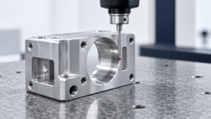
A CNC inspection report records a result under specific conditions. It does not automatically prove that the same component will fit after anodizing, remain flat after unclamping, or arrive without damage.
That distinction matters when buying precision components. A supplier can measure a bore correctly after machining, then send the part through a process that changes its diameter. An assembly team can receive individually conforming components whose combined tolerances leave insufficient clearance. Neither situation is solved by asking for a more detailed machining inspection report alone.
The practical question is: Does the acceptance plan cover the condition in which the component must function?
For buyers, this creates both a risk and an opportunity. Uncontrolled operations can turn acceptable parts into rejected assemblies. However, identifying those operations early allows machining allowances, finishing requirements, inspection stages, and packaging to work together.
The following five areas explain where that control commonly breaks down and how to address it without adding unnecessary inspection.
1. Final-State Inspection: Define What “Passed” Actually Means
Final-state inspection refers to verifying a component against its requirements after the operations that can affect its delivered dimensions, surfaces, cleanliness, or function.
“Inspection passed” is incomplete unless the report identifies the manufacturing stage. A measurement taken before coating answers a different question from one taken after coating. Likewise, a flatness result obtained while a thin plate is restrained does not necessarily describe its shape when released.
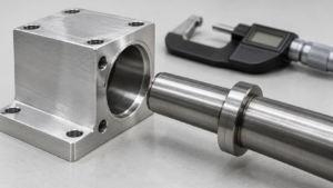
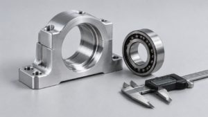
Consider an aluminum bearing housing. Its machining report may confirm bore diameter, hole position, and mounting-face flatness. The housing then undergoes deburring, blasting, anodizing, cleaning, and packaging. Each operation introduces a different consideration: edge geometry, surface texture, dimensional growth, contamination, or physical damage.
The drawing must connect these operations to acceptance. Otherwise, the machine shop may interpret dimensions as machining targets while the buyer expects them to apply to the finished component.
NASA’s anodizing specification illustrates this distinction: for relevant hard-anodized applications, it recommends specifying both final dimensions and machining dimensions. [NASA/JSC PRC-5006, Revision D] nasa.gov
This does not mean every feature requires inspection after every operation. A nonfunctional clearance pocket may need little additional attention. A bearing seat, sealing face, locating bore, or threaded interface deserves closer control because a small change can affect assembly.
A useful inspection plan separates three questions:
- Has the machining process produced suitable geometry for the next operation?
- Has the finishing process achieved its specified condition?
- Does the completed component meet its functional requirements?
These questions overlap, but they are not interchangeable. Coating certification does not establish bore conformity. A dimensional report does not establish cleanliness. An assembly trial does not establish coating thickness.
Buyers should also distinguish individual-part acceptance from assembly validation. A conforming bore and conforming shaft can still produce an unacceptable fit if their specified tolerance combination does not support the application. In that case, the problem lies in the interface definition rather than necessarily in manufacturing execution.
The opportunity is to concentrate inspection where it protects function. Instead of demanding a full dimensional report at every stage, identify which features can change and which changes matter.
For a repeat order, this approach also makes investigations faster. If machining-stage and final-stage results are traceable to the same component, the team can identify when a shift occurred rather than debating whose measurement is correct.
Action recommendation: Mark each critical drawing characteristic with its required acceptance condition, including manufacturing stage, restraint condition, and any functional verification.
2. Coating Growth: Small Thickness Changes Can Consume the Fit
Coating growth refers to the dimensional change created when a surface treatment builds above the original substrate surface, sometimes while also consuming part of that substrate.
The first mistake is treating every finish as a layer with the same growth behavior. Deposited metal and anodic oxide do not affect the original surface in identical ways.
For a uniformly deposited coating with thickness t, an external diameter increases by approximately 2t, while an internal diameter decreases by approximately 2t. These are geometric estimates: both opposing surfaces contribute to the diameter change. Actual deposition inside recessed features must still be established.
Sulfuric anodizing behaves differently. Anoplate describes conventional sulfuric anodic coatings as approximately two-thirds penetration into the substrate and one-third growth above the original surface. Its published thickness range is approximately 0.0001–0.001 inches, equivalent to 2.54–25.4 micrometers. These figures describe that process, not every anodizing condition. [Anoplate, Sulfuric Acid Anodizing] Anoplate, Inc.
Using the approximate one-third growth assumption, consider this illustrative bore:
| Parameter | Assumed value |
|---|---|
| Required finished diameter | 50.000–50.020 mm |
| Diameter before anodizing | 50.005 mm |
| Anodic coating thickness | 10 µm |
| Growth into the bore per side | 3.3 µm |
| Total diameter reduction | 6.6 µm |
| Estimated finished diameter | 49.9984 mm |
The calculation is:
Finished diameter = 50.005 − (2 × 0.33 × 0.010) = 49.9984 mm.
The initial measurement sits within the numerical finished-size limits, but the estimated finished bore falls below them. This is a calculated example based on stated assumptions, not a production measurement. [Calculation using the Anoplate growth approximation]
The reverse situation is equally important. Starting with a slightly oversized bore can be intentional when the drawing specifies a smaller finished diameter. Rejecting that bore against finished limits before anodizing would misunderstand the process plan.
When I reviewed the supplied research, I recalculated its bearing-bore example. Starting at 50.010 mm and subtracting 0.0066 mm gives 50.0034 mm, which remains inside the stated 50.000–50.020 mm range. I therefore treated that example as evidence of reduced dimensional margin, rather than evidence of rejection. This was a calculation check of the research, not a shop-floor experiment.
Nominal growth compensation is only the starting point. Pretreatment can remove material, coating thickness can vary, and internal surfaces may not behave like exposed surfaces. A successful sample does not establish that the same allowance will work across production.
Threads require particular attention. Coating affects flank engagement as well as major and minor diameters. An allowance copied from a plain cylindrical surface may therefore be unsuitable. The required thread condition must be agreed before and after finishing.
Masking can protect a precision interface, but it creates its own requirements: mask boundaries, transition areas, and protection of the uncoated surface. Machining after finishing may restore dimensions while removing protection locally.
Action recommendation: Agree finished dimensions, coating-thickness limits, masking boundaries, and machining allowances with both the machining supplier and finishing processor before production.
3. Residual Stress and Unclamping: Geometry Can Change After Cutting Stops
Residual-stress distortion refers to a change in component shape when manufacturing operations disturb internal stresses; unclamping deformation also includes elastic recovery after external restraint is removed.
These mechanisms can produce similar symptoms but require different corrective actions.
A thin plate may appear flat because a fixture forces it against a support. Once released, it springs back. Alternatively, removing material from a stressed blank can redistribute internal stresses and produce curvature even when clamping forces were modest.
Research on thin-walled machining identifies residual stress and machining strategy as important contributors to post-machining deformation. The practical implication is that cutting conditions and operation sequence influence the geometry available for final acceptance. [“Analysis of machining strategies in terms of residual stress and post-machining deformation of thin-walled element,” The International Journal of Advanced Manufacturing Technology]
A common mistake is finishing the component while it remains forced into the desired shape. The tool produces geometry relative to the restrained condition. Releasing the fixture then reveals a different free-state shape.
That does not mean free-state inspection is always the correct requirement. Some flexible components are designed to function under specified assembly restraint. Their acceptance may need a defined fixture or restrained condition. The problem is leaving that condition unspecified.
For buyers, three questions help separate the causes:
- Was the component measured while clamped or after release?
- Did its shape change after material removal, thermal processing, or both?
- Does the inspection condition represent the intended assembly condition?
A staged process can reduce uncertainty. Rough machining removes bulk material, intermediate release reveals movement, and subsequent finishing establishes critical geometry after that movement has been assessed.
However, adding a waiting period alone is not a universal stress-relief method. A controlled thermal treatment, a change in stock condition, and simply leaving a component on a bench are different interventions. Their suitability depends on material, geometry, and the manufacturing route.
Heat treatment requires the same discipline. Hardness and mechanical properties may meet specification while dimensional accuracy changes. Where practical, finish machining or grinding after thermal processing can establish critical interfaces. Where that sequence is impossible, the process must demonstrate acceptable distortion control.
There is no useful universal statement that heat treatment will distort every part by a fixed amount. Geometry, material condition, stress distribution, heating, cooling, and restraint all influence the result.
Buyers should also challenge generic rules about finishing stock. An allowance suitable for one thin-walled component may be excessive or insufficient for another. It must leave enough material for correction without creating unnecessary cutting forces or removing required features.
The commercial opportunity is substantial: a better operation sequence may protect geometry more effectively than specifying a tighter machining tolerance. The nominal tolerance is of little value if the component changes shape afterward.
Action recommendation: Require critical thin-walled or thermally processed parts to demonstrate conformity after the relevant release or treatment, using an explicitly defined inspection restraint condition.
4. Temperature: A Correct Measurement Can Describe the Wrong Condition
Thermal dimensional change refers to the expansion or contraction of a component as its temperature changes, including changes in clearance when mating materials expand at different rates.
Precision inspection depends on temperature because the object being measured has a temperature-dependent size. A warm component measured immediately after machining may not have the same dimensions after reaching equilibrium with the inspection environment.
A simple estimate uses:
ΔL = L × α × ΔT
Here, L is the starting length, α is the linear thermal expansion coefficient, and ΔT is the temperature change.
Assume a 100 mm component, an expansion coefficient of 23 × 10⁻⁶/°C, and a temperature increase of 40°C. The estimated expansion is:
100 × 23 × 10⁻⁶ × 40 = 0.092 mm.
These are explicitly selected engineering assumptions for illustration, not a certified material property or an observed test result. [Illustrative thermal-expansion calculation]
A change of 0.092 mm can exceed the dimensional margin available in a precision interface. Yet total expansion alone does not establish whether an assembly will tighten or loosen. That depends on which component forms the hole, which forms the shaft, and their respective temperatures and expansion behavior.
For example, if an aluminum housing expands more than its steel shaft under the same temperature increase, bore clearance generally increases. If an aluminum shaft expands inside a less-expansive housing, clearance can decrease. Reversing the component arrangement reverses the practical concern.
This is why statements such as “aluminum expansion makes the fit tighter” are incomplete.
Temperature differences within one component add another complication. A plate with uneven heating may distort rather than simply expand uniformly. The basic linear equation cannot describe every resulting change in flatness or alignment.
Measurement equipment introduces a further layer. The part, gauge, reference artifact, and inspection environment may not share the same temperature. Compensation can help, but only when its assumptions match the material and measurement situation.
For purchasing teams, the solution is not to specify an unrealistically narrow environmental range for every order. Separate the conditions needed for dimensional acceptance from those needed for functional performance.
A room-temperature inspection can establish conformity at an agreed reference condition. A separate engineering assessment or test can establish whether the interface remains functional across service temperatures. Combining these purposes into one unexplained tolerance invites disagreement.
Where temperature sensitivity is significant, ask for the measurement condition, stabilization approach, and material assumptions. For a working assembly, assess minimum and maximum clearance across the intended operating range.
Thermal movement can also be useful. Controlled heating or cooling may facilitate an intended interference assembly. The same physical effect becomes a process advantage when it is planned.
Action recommendation: Define the dimensional inspection condition, then separately verify critical fits across the specified assembly and operating temperatures.
5. Burrs, Cleanliness, and Packaging: Protect Function Beyond the Drawing Dimensions
Functional delivery condition refers to the combined dimensional, surface, cleanliness, and physical condition that allows a component to be assembled and used as intended.
A part can meet its measured dimensions and still fail this requirement.
A burr at a seating edge can prevent full contact. A loose chip can remain inside an intersecting passage. Residue can contaminate a bonding surface. A dent acquired during transport can damage an otherwise conforming sealing interface.
These defects often escape a dimensional report because that report was never designed to detect them. Measuring a bore at selected locations does not necessarily reveal a folded burr at an intersection or contamination deeper inside a passage.
“Deburr all edges” is a useful general instruction, but it may not adequately control a critical interface. Buyers should identify where edge condition affects assembly and where excessive edge removal would also be harmful.
A seal entry may require a controlled lead-in. A locating shoulder may require limited edge break. An internal passage may require verification that loose material has been removed. Applying the same aggressive deburring method everywhere can solve one problem while creating another.
Surface preparation likewise belongs in the process definition. NASA’s anodizing guidance explains that surface texture is reproduced rather than leveled by anodizing, and preparation influences final roughness. A finishing operation should therefore not be assumed to conceal unsuitable machining marks. [NASA/JSC PRC-5006, Revision D] nasa.gov
Cleanliness requirements should follow the application. A hydraulic component, a bonding interface, and a general mounting bracket do not necessarily need identical controls. Where contamination affects function, specify the relevant acceptance method rather than relying on a visual statement that the part “looks clean.”
Drying deserves attention as well. A component can have acceptable external surfaces while liquid remains in a blind feature. Cleaning, verification, drying, and packaging should form one coordinated sequence.
Packaging then has to preserve that verified condition. Individual separation protects parts only if they cannot move into contact during handling. A protective cap helps only if it stays in place and does not introduce contamination. A package that supports a robust body may still load a thin flange incorrectly.
For buyers, a practical control table is more useful than a generic request for “export packing”:
| Functional risk | Requirement to define |
|---|---|
| Damage to sealing faces | Contact-free protection of designated surfaces |
| Bent thin sections | Support locations and permitted restraint |
| Thread damage | Suitable retained thread protection |
| Contamination in passages | Cleanliness verification and closure method |
| Surface abrasion | Individual separation and movement control |
| Moisture exposure | Application-appropriate protection and packaging |
Inspection ownership must also be clear. If the machine shop, finishing processor, and packing team each assume another party performs final acceptance, the completed component may leave without an integrated check.
The efficient approach is to inspect after the last operation capable of creating the relevant defect, then protect that condition through shipment. Packaging validation should reflect the actual distribution route and component sensitivity.
Action recommendation: Add a final acceptance checklist covering critical edges, cleanliness, surface condition, and packaging, with a named owner for release.
الأسئلة الشائعة
A: It proves conformity only for the characteristics and conditions covered by that measurement. Assembly also depends on mating-part tolerances, coatings, edge condition, temperature, and the intended restraint. Review the interface requirements before assuming that additional CMM measurements will resolve the problem.
A: No. Masking is one option alongside controlled machining allowances or approved finishing after anodizing. The choice depends on dimensional requirements, wear, corrosion protection, and process capability. Define the required condition of the hole and its transition to coated surfaces before selecting the method.
A: No. Deposited coatings and conversion processes affect dimensions differently. Geometry, pretreatment, thickness variation, and access to internal surfaces also matter. Use a process-specific allowance supported by the processor’s capability, then verify the finished feature.
A: The fixture may temporarily force it into shape. Releasing it allows elastic recovery and potentially exposes distortion associated with residual stresses. Define whether acceptance applies in the free state or under specified restraint, and inspect in that condition.
A: Usually, no. Select inspection stages according to which operations can affect critical requirements. This focuses effort on meaningful changes while avoiding repeated measurements of stable, noncritical features. Final acceptance must still cover the completed component’s required condition.
A: Identify critical finished dimensions, coating requirements, masking, thermal processing, measurement conditions, edge requirements, cleanliness, and packaging. Ask the supplier to flag conflicts before quotation and explain how the proposed manufacturing sequence will preserve the required interfaces.