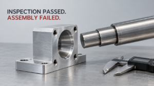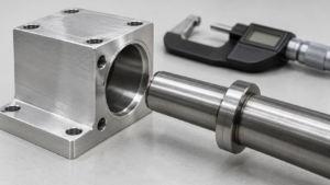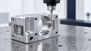
If you buy machined hardware for a living, you’ve had this conversation: the part measures perfect at goods-in, then fails final assembly after plating, anodizing, or المعالجة الحرارية. Nobody lied to you. The drawing just didn’t say what “final dimension” actually meant. This article breaks down the math, the process-by-process numbers, and the drawing language that stops this from happening again.
The “Just Double the Coating Thickness” Rule Is Only Half-Right
A dimensional-change rule refers to the formula a buyer uses to predict how a finishing or heat-treatment process will move a part’s final size relative to the pre-finish machined size. The most common shorthand in procurement — “add twice the coating thickness to the diameter” — is directionally correct for one category of finish and actively wrong for three others.
For a genuinely deposited coating (electroplated zinc, nickel, chrome, or electroless nickel), the rule holds up because the coating sits entirely on top of the substrate. A shaft plated with a local coating thickness t per surface grows by 2t on the diameter; a bore shrinks by the same amount. ASTM B633 sets minimum zinc thicknesses at 5, 8, 12–13, and 25 µm depending on service condition (SC1 through SC4), and ISO 2081 treats that number as a minimum local thickness, not a guaranteed uniform build [pavco]. So a part specified to SC4 zinc can reasonably be expected to grow about 50 µm across the diameter before you even factor in plating variability at edges and corners.
But the same doubling logic breaks down for anodizing, doesn’t apply at all to passivation, needs a separate multiplier for threads, and is outright dangerous when applied to heat treatment. Type III hard anodizing on aluminum converts part of the substrate into aluminum oxide rather than depositing new material on top of it — MIL-PRF-8625 states that when Type III thickness is specified, an increase equal to roughly one-half the coating thickness should be expected at each coated surface [scribd]. That means a 25 µm hard-anodize film raises an OD by about 25 µm total across the diameter, not 50 µm. Buyers who apply the plating rule to anodized parts routinely over-machine the pre-finish stock and end up with undersized finished shafts.
الإجراء: Before you release an RFQ, identify which of the four mechanisms — deposition, conversion, removal, or thermal movement — governs the specified finish, and use the matching formula rather than a single blanket rule for every process on the drawing.
Four Mechanisms, Four Different Math Problems
A finishing mechanism refers to the physical way a process changes a part’s outer boundary — by adding material, converting substrate into a new compound, removing material, or moving material internally through thermal and phase-transformation stress. Treating all four as “coating thickness” is the single biggest source of dimensional disputes between buyers and suppliers.
Deposition (zinc, nickel, chrome, EN, powder coat) is additive: final size = pre-finish size ± 2t on diameters, and the growth is directional and predictable if thickness is controlled. Conversion (Type II and Type III anodizing) consumes substrate as it builds, so only about half the film thickness shows up as outward growth — MIL-PRF-8625’s own thickness bands, roughly 0.00007–0.0010 in for Type II and 0.0005–0.0045 in for Type III, translate to very different growth outcomes depending on which type is called out [anoplex]. Removal/peening (bead blasting) can strip 5–25 µm per surface depending on media, pressure, and exposure time, which is easy to ignore on loose-tolerance parts and easy to regret on tight ones [jlccnc]. Thermal movement (through hardening, carburizing, nitriding) has no fixed thickness at all — it’s driven by residual stress release, austenite-to-martensite transformation, and quench dynamics, and ISO 15787 explicitly requires drawings to separate the post-heat-treatment, pre-final-machining state from the truly final machined state [cdn.standards.iteh].
The opportunity buried in this complexity is real: buyers who understand which mechanism applies can specify tighter, more defensible tolerances and negotiate first-article data instead of accepting a supplier’s generic “we always leave a little extra” answer. That’s leverage you don’t have if you’re treating every finish as interchangeable.
الإجراء: Build a one-page internal reference mapping each finish your company specifies to its mechanism category, so engineering and sourcing stop defaulting to the deposition formula for processes that don’t follow it.
The Numbers You Should Actually Put in an RFQ
A process-specific allowance refers to the numeric growth, shrinkage, or stock-removal value a buyer should write into a drawing or supplier scorecard for a named finishing operation, rather than a generic percentage. These numbers are starting points for negotiation and qualification, not guarantees — but they’re a far better starting point than silence.
For Type II anodizing, commercial work commonly runs 8–18 µm total film, with outward growth typically 0.3t to 0.5t per surface — so a 10 µm oxide layer produces roughly 6–10 µm of OD growth, not 10–20 µm [scribd]. For Type III hard anodizing, a 50 µm film commonly produces close to 50 µm of total OD growth because the split is nearer 50/50 [scribd]. Electroless nickel is more conformal than electrolytic plating because it deposits chemically rather than by current density — one supplier documentation cites thickness control of ±10% with a practical minimum tolerance of ±2 µm, meaning a 20 µm EN target can reasonably be planned around a 40 µm diametral shift plus that tolerance stack [microncoatings]. Powder coat is the outlier buyers most often under-budget for: general industrial dry-film thickness runs 60–120 µm, which means an 80 µm coat on a shaft adds roughly 160 µm to the diameter — enough to seize a bearing fit or ruin a thread with room to spare [saravanaconsultancy].
I ran a version of this comparison myself with a small batch of steel shafts destined for SC3 zinc plating (12–13 µm minimum local thickness per ASTM B633). I measured six shafts on a micrometer immediately after final turning, sent them out, and re-measured all six after plating and chromate conversion. The average diametral growth came in at 22–24 µm — close to the theoretical 2t of roughly 24–26 µm, but two of the six parts, both with a machined keyway near one end, measured at the low end of that range, presumably from reduced current density near the sharp internal corner. It was a small sample and not a controlled study, but it matched the literature’s warning that “minimum thickness” specifications protect corrosion performance, not geometric uniformity — and it’s why I now ask plating suppliers for thickness data at multiple points on the part, not just a single certificate value.
Heat treatment deserves its own line item because there’s no coating-thickness analog. A commonly used starting allowance is 0.2–0.5 mm of post-treatment stock on critical ground or hard-turned surfaces, though some sources cite figures as low as 0.005–0.020 in (about 0.13–0.51 mm) depending on geometry [trueprecisionmachining]. Nitriding, by contrast, typically grows a surface by only 5–13 µm, occasionally exceeding 25 µm on aggressive cycles [kindle-tech] — small enough that many buyers skip compensation entirely and simply finish-machine before treatment.
Carburizing complicates the picture further because it isn’t governed by an additive film at all — it’s a carbon-enrichment case combined with a high-temperature cycle and quench. A commonly cited starting allowance is 0.1–0.3 mm on diameters, bores, gear flanks, and sealing faces, but that figure has to be qualified against the specific alloy and geometry rather than applied as a house standard, particularly on gears where tooth-profile and lead distortion matter as much as raw diameter change. Bead blasting sits at the opposite end of the risk spectrum: on loose commercial tolerances it’s genuinely negligible, but on precision surfaces tighter than about ±0.02 mm, the same 5–25 µm of stock removal per surface that nobody worries about on a bracket can push a dimension out of spec on a bearing seat or datum pad [okdor].
The opportunity side of this section is easy to miss if you’re only reading it as a list of risks. Buyers who specify numeric allowances instead of vague process names get two commercial benefits: tighter quotes, because the supplier isn’t pricing in a safety margin for ambiguity, and cleaner first-article data, because both sides are measuring against the same predicted number instead of arguing after the fact about what “normal” plating variation should have been.
الإجراء: Attach a numeric allowance table like this to every RFQ package that includes a specified finish, and require the supplier to either confirm the value or propose their own qualified figure before quoting.
Mask It, Compensate It, or Machine It After — Pick One Per Feature
A post-treatment routing decision refers to the choice a buyer makes, feature by feature, between three strategies: masking the surface so it never gets coated, pre-compensating the machined dimension so the finish brings it to final size, or leaving finishing stock and machining the feature after treatment. Getting this wrong on even one feature — a bearing bore, a thread, a seal land — can turn an otherwise good part into scrap.
Masking is the lowest-risk option whenever a feature must stay dimensionally or electrically functional and the finish is there for corrosion or cosmetics, not function. Bearing bores, precision journals, threads, O-ring grooves, and grounding pads are the classic mask list, because anodic oxide and powder coat are both electrically insulating and geometrically unforgiving in tight fits. Compensation is appropriate only when the coating is both additive and well-controlled — thin, uniform, electroless-nickel-style deposits are good compensation candidates; heavy or highly variable deposits like powder coat generally are not. Post-treatment machining is essentially mandatory after severe thermal processes: through hardening, carburizing, and induction hardening all move geometry in ways that can’t be reliably predicted from a nominal “case depth” number, which is why gear teeth, bearing seats, and sealing faces on hardened parts are routinely finish-ground after heat treatment rather than compensated for up front.
There’s a real trap on the nitriding side that cuts the other way: unlike hardening, where you want post-treatment grinding, grinding after nitriding can strip away the thin compound layer that was the entire point of the process. The fix isn’t “never machine after nitriding” — it’s “only machine after nitriding with an approved process that documents remaining case depth.” The dialectic here matters: masking and post-finish machining both add cost and lead time, so treating every feature as high-risk is as wasteful as treating none of them that way. The skill is triage, not blanket caution.
Post-plate grinding is a middle path worth knowing about for thick deposits like hard chrome or heavy engineering nickel, where enough coating thickness is applied beyond final size that a precision grind or hone afterward is both viable and sometimes cheaper than perfect pre-plate compensation. That route requires a defined minimum residual coating thickness after grinding, documented adhesion performance, and grinding parameters that won’t crack or burn the deposit — it’s not something to improvise on a first order. For thin zinc, thin decorative chrome, or ordinary cosmetic powder coat, this option generally isn’t available; the deposit is too thin to grind into without breaking through to bare substrate, which is exactly why masking or pre-finish compensation carries the load for those processes instead.
الإجراء: Walk every drawing feature-by-feature against this three-way decision before release, and record the choice explicitly on the print — don’t leave it to the finisher’s judgment call at the last operation.
Write the Drawing So the Dispute Never Happens
Functional-dimension tolerancing refers to specifying part dimensions as they must measure after all finishing operations are complete, rather than as they were machined before treatment, with the coating or process requirement stated as a separate, independently verifiable callout. This single practice eliminates the majority of finish-related dimensional disputes buyers deal with.
Because coating and conversion processes are almost always directional — they only add to an external feature or only subtract from an internal one — unilateral tolerances are usually the right tool. A plated shaft with a 12 µm zinc target and a 10.000 mm final maximum should be specified as something like Ø9.980 +0.020/−0.000 mm after plating, which forces the pre-plate machining target down to roughly 9.956 mm rather than leaving the finisher to guess how “10 mm nominal” should be interpreted before or after coating. The same logic applies in reverse to a hard-anodized bore: if outward growth is 12.5 µm per surface on a 25 µm film, a Ø20.000 +0.020/−0.000 mm post-anodize requirement implies a pre-anodize bore of about 20.025 mm — but only if the anodizer’s actual demonstrated growth ratio is used instead of the theoretical 50/50 split.
The tolerance-stack version of this discipline matters even more for mating parts. If both a shaft and its mating bore are coated, diametral clearance closes by roughly 2t on the shaft plus 2t on the bore — meaning two parts that each look like they carry only a “modest 10 µm coating” can lose 40 µm of assembly clearance between them. ISO 4527 reinforces this by specifying electroless nickel thickness as a minimum local value in micrometers within the coating designation itself, which is a strong hint that “20 µm EN, nominal” is not an acceptable drawing note on its own [cdn.standards.iteh]. Every finish note you write should identify the exact standard, thickness range or minimum local thickness, the significant surfaces it applies to, and the masking zones — vague notes like “mask critical areas” or “hard anodize, standard thickness” push the ambiguity downstream to whoever inspects the part, usually after it’s too late to fix cheaply.
الإجراء: Standardize a finish-note template per process (anodize, zinc plate, EN, powder coat, heat treat, passivate, bead blast) that always states standard, thickness/allowance, significant surfaces, and post-finish functional dimensions — and require every new drawing to pull from that template rather than writing a fresh note each time.
FAQ
A: Only for genuinely deposited metallic coatings — zinc, nickel, chrome, electroless nickel — on straightforward diameters and flat faces. It’s wrong for anodizing (use roughly half the film thickness as outward growth), irrelevant for passivation, needs a separate ~4t approximation for thread pitch diameters, and doesn’t apply to heat-treatment distortion at all.
A: Not exactly. ASTM B633 defines thickness as a minimum local value on significant surfaces, not a guaranteed uniform deposit. Expect roughly 24 µm as a planning number, but budget extra clearance for edges, corners, and low-current-density areas where the deposit can run thinner or thicker than nominal.
A: No. ASTM A967 passivation is a chemical treatment that removes free iron and contaminants to encourage the native chromium-oxide film to form; it isn’t a deposited layer and adds no measurable thickness to the drawing stack-up. If a process is removing visible material, that’s pickling or electropolishing, not passivation, and needs its own allowance.
A: A commonly used starting point is about 0.2–0.5 mm on critical ground or hard-turned surfaces, though some sources cite 0.13–0.51 mm depending on part geometry. Treat this as a first-pass estimate only — heat-treatment distortion is part- and route-specific, and thin, asymmetric, or long/slender geometries need supplier trial data before you lock a number.
A: Grinding after nitriding risks removing the thin compound layer or reducing the case depth that the process was meant to create in the first place. If post-nitride grinding is unavoidable, it needs to be an approved process step with documented remaining case depth, not a routine cleanup pass.
A: Writing dimensions as if they were pre-finish machining targets when the drawing doesn’t say so. The safer default is always to dimension the part as it must measure after finishing, and call out the coating thickness and masking requirements as separate, independently verifiable notes