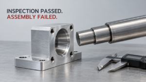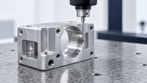
If you buy CNC parts internationally, you’ve seen this pattern: the First Article Inspection (FAI) report comes back clean, you release the PO for 5,000 units, and three weeks later 200 parts from batch four are out of tolerance on a critical bore. Nobody changed the drawing. Nobody changed the material spec. So what happened?
The short answer: FAI never tested for what actually breaks tolerance in volume production. Below are the five mechanisms that separate “first piece good” from “process capable,” what the data says about each, and what to put in your next RFQ so you stop finding out the hard way.
1. What First Article Inspection Actually Proves
First Article Inspection refers to the verification that one part — or a small handful of parts — produced on a specific machine, with a specific fixture, a specific tool set, at a specific thermal state, and under one operator’s setup, conforms to the drawing. It does not refer to, and was never designed to prove, that the next 999 parts will hold the same tolerance once the spindle heats up, the tool dulls, the fixture gets reclamped a hundred times, and the material comes from a different heat lot.
Dimensional drift across a production run is essentially the sum of several independent error sources stacking and interacting with each other:
E(total) ≈ E(thermal) + E(tool wear) + E(tool deflection) + E(runout) + E(fixture) + E(machine geometry) + E(residual stress) + E(measurement/offset)
NIST’s machine tool performance research lists positioning accuracy, repeatability, geometric error, spindle rotation error, thermal error, probing performance, fixture location, and dynamic motion error as the standard set of factors that determine final part quality [NIST]. None of these are evaluated by a one-piece FAI. A first article typically uses a fresh tool, a carefully seated fixture, and a machine that may or may not be thermally stable — conditions that do not represent piece 400 of an overnight run.
There’s a dialectical point worth making here: this gap isn’t purely a risk to manage — it’s also a filter you can use to separate good suppliers from mediocre ones. Any shop can produce one good part. Far fewer can show you Cpk data across a stabilized run. That difference is exactly the leverage point buyers have in supplier selection, and it costs the supplier nothing but honesty to disclose.
Acción: Before qualifying a new supplier for a tight-tolerance job, ask for capability data (Cpk/Ppk) from a simulated or real production run — not just the FAI report. If they can’t produce it, that itself is useful information.
2. Thermal Drift Is the Most Underestimated Variable
Thermal drift refers to the dimensional change in a workpiece, machine structure, and measuring instrument that occurs whenever temperature deviates from the 20°C reference standard used on virtually all engineering drawings. It’s underestimated because it’s invisible on the inspection report — a part can be perfectly “in spec” at 20°C and read as out-of-tolerance at 26°C, or vice versa, without anything actually being wrong with the machining.
The math is simple but the consequences aren’t: ΔL = α × L × ΔT. Aluminum’s typical coefficient of thermal expansion is about 23.1 ppm/°C, versus roughly 11.5 ppm/°C for steel — meaning aluminum parts move about twice as much as steel parts for the same temperature swing [NIST]. Run the numbers on a 200 mm aluminum part measured 5°C above the 20°C reference: ΔL = 23.1×10⁻⁶ × 200 × 5 = 0.0231 mm. If the drawing tolerance is ±0.020 mm, a part that was genuinely correct at 20°C now reads over the upper limit — and worse, an operator chasing that reading with a tool offset will end up with a genuinely undersized part once it cools [NIST/NCSLI]. Scale that up: a 500 mm aluminum part at an 8°C offset shifts by roughly 0.092 mm — enough to blow past hole-position, flatness, or profile tolerances on most mechanical drawings [NIST/NCSLI].
This isn’t only a workpiece problem. The machine itself is a heat source. Spindle bearings, ballscrews, and motors all grow as they run, and Z-axis spindle growth directly shifts pocket depth, step height, and counterbore depth relative to program position. Haas publishes a specific thermal growth test procedure for exactly this failure mode [Haas], and Mazak markets thermal displacement control systems specifically to suppress spindle-tip position drift as spindle speed and internal temperature change [Mazak] — which tells you the OEMs themselves treat this as a first-order production issue, not a theoretical one.
I ran into this firsthand while reviewing a batch-rejection case for a 6061-T6 aluminum bracket with a ±0.010 mm bore callout. The supplier’s FAI report showed the bore at nominal, measured on a CMM in a climate-controlled room the morning after machining. But their in-process spot checks — taken straight off the mill, on parts still warm from cutting — were consistently 0.012–0.015 mm larger than the cooled CMM readings. Nobody had flagged it as a problem because every part still “passed” on paper once it cooled. The real issue only surfaced when an operator, working a night shift with no cooldown window, adjusted the boring bar offset based on a hot reading. That one adjustment produced 340 undersized parts before anyone caught it. The fix wasn’t a better machine — it was a written rule: no offset changes based on measurements taken before a part reaches ambient temperature.
Acción: For any aluminum or large-envelope part with tolerances tighter than ±0.05 mm, require the supplier to record and report the workpiece temperature at the time critical dimensions were measured — and prohibit tool-offset changes based on unstabilized readings.
3. Tool Wear, Deflection, and Runout Compound Each Other
Tool wear, deflection, and runout refer to three distinct but interacting mechanisms: the gradual dulling of a cutting edge over time, the elastic bending of a tool under cutting force, and the off-center rotation of a tool or holder relative to true spindle centerline — all of which shift the effective cutting position as a run progresses, none of which a first article captures because a first article is almost always cut with a fresh tool.
Wear is the most predictable of the three and the easiest to control on paper, but it rarely acts alone. As a cutting edge dulls, cutting force and heat both rise, which increases tool deflection and can push thin walls further out of position — a feedback loop where one error source amplifies another [Renishaw]. Deflection itself follows a cube-law relationship with tool overhang (δ ∝ FL³/EI): tripling an end mill’s stickout from 20 mm to 60 mm can theoretically increase deflection by roughly 27x, all else held equal [Georgia Tech][NIST]. That’s not a rounding error on a deep-pocket wall dimension — it’s the difference between a part that’s in spec and one that isn’t.
Runout adds a third failure mode that’s easy to miss because it often passes a static check. Spindle bearing wear, a contaminated toolholder taper, a worn collet, or a tool that isn’t fully seated can all cause one flute of a multi-flute cutter to take a deeper cut than the others. Renishaw’s guidance notes that dynamic, at-speed checks catch runout and holding inconsistencies that static setup checks miss entirely [Renishaw] — and the downstream symptoms (oversized bores, poor roundness, multi-lobed hole walls, uneven flute wear) look identical to tool wear on an inspection report, which is exactly why root-cause analysis on out-of-tolerance batches so often stalls out.
Here’s the dialectical read: none of this is a reason to distrust CNC suppliers broadly — it’s a reason to be specific about which parts warrant which level of scrutiny. A short, low-aspect-ratio bracket in mild steel doesn’t need the same tool-life discipline as a deep aluminum pocket with 0.01 mm wall tolerances. Spending audit time proportional to geometric risk, rather than uniformly across every SKU, is the efficient version of this control.
Acción: For deep-pocket, thin-wall, or precision-bore parts, require the supplier to specify maximum tool overhang and a hard tool-life limit (by part count or cutting time) in writing — not “operator judgment.”
4. Fixture Deformation and Residual Stress Cause Springback After Release
Fixture deformation and residual stress refer to two distinct effects — elastic distortion of a workpiece caused by clamping force during machining, and dimensional movement caused by the release of internal material stresses when material is removed — both of which share a common, dangerous signature: the part measures correctly while still clamped in the fixture, and only shows out-of-tolerance once it’s released and returns to its free state.
Fixture-induced deformation is well documented in machining research: thin plates, shells, rings, and large aluminum frames can all bend elastically under vise pressure, clamps, or vacuum fixtures, and if a part is machined to size while distorted, it springs back to a different shape the moment clamping force is removed [HAL/LaBoMaP]. This is compounded by residual stress carried in the raw material itself — from rolling, extrusion, forging, casting, welding, or tratamiento térmico — which rebalances internally whenever significant material is removed from one side of a part, most commonly in single-side deep pockets, long extrusions, and large frames machined from plate [NIST][NSF]. A part can pass every dimension check on the machine and still warp measurably after unclamping, sitting overnight, or a downstream heat-treat step.
Material choice changes the odds considerably. Aluminum plate and extrusions carry meaningfully higher residual-stress and clamping-distortion risk than steel bar stock or pre-stress-relieved forgings [NIST]. That’s not an argument against aluminum — it’s a reminder that the process route matters as much as the material spec. A supplier running symmetric roughing passes, stabilization steps between roughing and finishing, and a genuine free-state inspection is managing the same physics a supplier skipping those steps is ignoring; the raw material cost is identical, but the failure rate is not.
Acción: For thin-wall, sheet-metal-derived, large-frame, or ring-shaped aluminum parts, require free-state (post-unclamping) CMM data in the inspection report — in-fixture measurements alone are not sufficient evidence of conformance.
5. A Real Control Plan Replaces “Inspect to Drawing”
A control plan refers to the documented set of process parameters, measurement methods, sampling frequencies, tool-life limits, and reaction procedures a supplier formally commits to for holding dimensional stability across an entire production run — it is not a synonym for “100% inspection” or “per drawing,” phrases that describe an outcome without specifying how it’s achieved or verified.
NIST’s machine tool evaluation framework treats positioning and geometric error, spindle rotation error, circular interpolation, fixture alignment, and on-machine probing as items that require ongoing verification, not one-time certification [NIST]. Applied to a supplier relationship, that means a usable control plan should specify, at minimum: tool identification and life limits with defined change triggers; offset-change authorization and logging (who can adjust, by how much, with what justification recorded); warm-up and cold-start-versus-thermally-stable verification for tight-tolerance jobs; fixture version control with clamping force and sequence documented; and a defined reaction plan — stop, quarantine, trace back to the last known-good part, root-cause, re-release with a fresh first article — triggered by any out-of-tolerance result, tool break, machine crash, or material lot change [Renishaw][Mitutoyo].
The dialectical framing matters here too: yes, this is more paperwork than “we inspect every part,” and yes, a supplier will sometimes push back on the added documentation burden. But the alternative cost is a field failure, a warranty claim, or a full-batch scrap event traced back to an undocumented offset change nobody can explain three weeks later. For medical, aerospace, or safety-critical hardware, this isn’t optional overhead — it’s the cheapest insurance available, because it costs the supplier engineering time, not tooling or material.
Acción: Don’t accept “inspect to drawing” as a control plan line item in a quote or quality agreement. Require the specific elements above — tool-life triggers, offset-change logs, cold/warm verification, fixture version control, and a written reaction plan — as explicit clauses in the RFQ or supplier quality agreement before award.
FAQ
A: Not necessarily. FAI verifies one part under near-ideal, closely monitored conditions. It doesn’t test for tool wear over hundreds of cycles, machine thermal drift, or fixture repeatability across many reclamping cycles — all of which only show up in sustained production.
A: Aluminum alloys carry roughly double the thermal expansion risk of steel for the same temperature swing, since aluminum’s coefficient of thermal expansion (~23.1 ppm/°C) is about twice that of typical steel (~11.5 ppm/°C). Large aluminum parts and precision aluminum bores are the highest-risk category.
A: No — reserve that request for tight-tolerance, high-value, or safety-critical parts. For low-risk, loosely toleranced geometries, standard sampling inspection is usually proportionate and Cpk requests add cost without meaningfully reducing risk.
A: A requirement for free-state (post-unclamping) inspection data on thin-wall, sheet, or large-frame parts, combined with a documented tool-life and offset-change log. Together these catch the two most common — and least visible — sources of batch drift: fixture springback and undocumented human intervention.
A: For parts with tolerances tighter than roughly ±0.05 mm, especially in aluminum or with dimensions over 300 mm, yes — it’s a low-cost requirement. For looser-tolerance, smaller steel parts, it’s usually unnecessary overhead.
A: Ask for the traceability data the control plan should already require: tool ID and cycle count at time of the failed parts, fixture version, offset-change log, and workpiece/environment temperature at measurement. If a supplier can’t reconstruct this after the fact, that gap is itself the finding — it means their control plan wasn’t actually being followed.