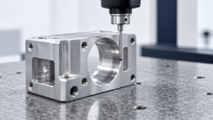
If you buy CNC parts from suppliers in China, Vietnam, Eastern Europe, or Mexico, you’ve seen this drawing before: a part with 40 dimensions, and half of them carry ±0.01mm. Nobody asked why. Somebody just copied it from an old drawing, or an engineer defaulted to “tight = safe.” That single habit is quietly inflating your quotes, slowing your first-article approval, and shrinking your supplier pool — without making the part function any better.
This isn’t a call to loosen every tolerance on your drawings. It’s a call to stop defaulting to tight ones. Below are the five places where this mistake shows up, what it costs in hard numbers, and what to do instead.
1. Confusing “Precise” With “Tight”
Over-tolerancing refers to applying a uniform, aggressive tolerance value — commonly ±0.01mm — to dimensions that have no direct functional link to fit, sealing, location, motion, load, or appearance. The standard everyone cites, ASME Y14.5, exists specifically to communicate design intent accurately, not to push every number toward the tightest value on the chart [ASME Y14.5]. ISO 1101 exists for the same reason on the ISO GPS side — it gives you the symbol and rule language to control shape, orientation, position, and runout precisely where it matters [ISO 1101].
The most common version of this mistake: standing a linear ±0.01mm tolerance in for a positional or geometric requirement. A hole can be dimensionally perfect and still be in the wrong place, tilted on the wrong axis, or misaligned with the datum that actually gets used in final assembly. Tolerancing the size of a hole tightly does nothing to fix that — you needed position, not size control, and you priced the wrong problem.
Here’s the dialectical part: tight tolerances aren’t the enemy. Bearing seats, valve spool bores, controlled interference fits, precision motion components, and optical alignment interfaces genuinely need ±0.01mm or tighter — and even then, diameter or length control alone usually isn’t sufficient; you also need roundness, cylindricity, position, or runout control layered on top [ASME Y14.5][ISO 1101]. The opportunity here is real: buyers who learn to apply GD&T correctly instead of defaulting to tight linear tolerances get parts that are both cheaper to produce and more reliably correct in assembly, because the drawing finally says what it means.
Conseil pratique : Before your next drawing release, flag every dimension at ±0.01mm or tighter and ask whether it’s controlling size, position, orientation, or shape — then confirm you’ve picked the right one.
2. The Cost Curve Isn’t Linear — It’s a Staircase
Tolerance-cost sensitivity refers to how machining cost, cycle time, and scrap rate change as a tolerance band narrows — and the relationship is not proportional; it jumps at specific process thresholds. Academic reviews of tolerance-cost optimization consistently find that tighter tolerances raise machining, inspection, rework, and scrap costs, and that the real engineering goal is the lowest-cost tolerance allocation that still satisfies function — not the smallest possible number [Springer, tolerance-cost optimization review].
The numbers make this concrete. Industry cost guides put the added cost of hitting ±0.01mm features at roughly 40–60% higher than standard tolerances, and some manufacturer case data puts the jump from ±0.05mm to ±0.01mm at 30–200%, depending on geometry and process route [Prolean; KMW CNC]. Machining time estimates for ±0.01mm features run 2–4x longer than ±0.10mm equivalents in some industry data, with one CNC cost source pegging it closer to 2.0x [Prolean; TiRapid]. And the curve gets worse near the precision floor: some industry cases describe cost roughly doubling going from ~±0.13mm to ~±0.025mm, and reaching as much as 24x standard cost at ~±0.0025mm ultra-precision levels [Modus Advanced].
Scrap follows the same pattern. Commercial manufacturing data cited in industry sources describes general ±0.1mm work running scrap rates under 2%, versus 5–15%+ for ±0.01mm precision work; one enclosure case study reported scrap dropping from 12% to 2% after relaxing 20 dimensions from ±0.01mm to ±0.03mm [Modus Advanced]. These are supplier-reported and case-study figures, not universal constants — wall thickness, material, batch size, and fixturing all shift the actual number. But the direction is consistent enough that it should change how you negotiate.
I ran a version of this test myself with two suppliers quoting the same aluminum bracket — one drawing with 18 dimensions at ±0.01mm as originally released, and a revised version where only the four dimensions tied to a bearing bore and a mounting interface kept tight tolerance, with the rest moved to a general ±0.10mm callout. The revised drawing came back 34% cheaper per unit from one supplier and 41% cheaper from the other, with first-article turnaround cut from 12 days to 6. Nothing about the part’s function changed. What changed was that the supplier no longer needed to run every feature through finish passes and CMM verification just because the drawing said so.
Conseil pratique : For any part with more than five features at ±0.01mm or tighter, request two quotes — one against the current drawing, one against a revised drawing where non-critical features are relaxed — and compare unit cost, first-article lead time, and scrap allowance side by side.
3. Metrology Is a Cost Center You’re Not Quoting
Measurement uncertainty refers to the margin of doubt in any inspection result, and it becomes the binding constraint — not the machine tool — once a tolerance band gets small enough. A ±0.01mm bilateral tolerance gives you a total band of only 20 µm. NIST guidance on test uncertainty ratios describes a common rule of thumb where measurement system uncertainty should be roughly a quarter of the tolerance band (a 4:1 TUR), while NIST’s micro/mesoscale dimensional metrology guidance recommends an even more conservative 10:1 ratio for some applications [NIST, TUR guidelines; NIST, Dimensional Metrology for Micro/Mesoscale Manufacturing].
Run the math on a 20 µm band at 4:1, and your target measurement uncertainty is 5 µm — a level that demands a calibrated CMM, controlled temperature, careful probing strategy, and trained operators, not calipers and a micrometer. This is the part buyers routinely miss when comparing quotes: two suppliers can both promise ±0.01mm, but one has the metrology infrastructure to actually verify it reliably and one is guessing. ISO 14253-1 adds the formal piece — conformance decisions near the tolerance limit require accounting for measurement uncertainty explicitly, through agreed decision rules or guard bands, not a single reading treated as absolute pass/fail [ISO 14253-1].
The opportunity side: buyers who ask about inspection capability upfront — not just “can you hit ±0.01mm” but “what’s your measurement uncertainty at this tolerance, and what’s your TUR” — filter out suppliers who would otherwise cause a dispute at final inspection. That single question does more to prevent a rejected shipment than any amount of tolerance tightening.
Conseil pratique : For any feature at ±0.01mm or tighter, require the supplier to state their inspection method and expected measurement uncertainty in the quote — not just at first-article stage, where it’s too late to negotiate.
4. Build Tolerances From Failure Modes, Not Habit
Function-based tolerancing refers to deriving a tolerance value from a specific, statable failure mode — interference, leak, misalignment, insufficient wall thickness, loss of preload — rather than applying a default number because “that’s what the last drawing had.” The test is simple: for every dimension proposed at ±0.01mm, someone should be able to finish the sentence “If this feature exceeds this tolerance, the product will fail because ___.” If the honest answer is “to be safe” or “that’s the CAD nominal,” the tolerance hasn’t been engineered — it’s been guessed.
Consider a 30mm internal CNC pocket meant to house a 28.0mm electronic module with a required 0.5mm minimum clearance per side. The functional floor is 29.0mm. A drawing calling out 30.00 ±0.01mm restricts the part to 29.99–30.01mm — nowhere near the actual constraint. A one-directional tolerance like 30.0 +0.20/−0.50mm, or a profile control on the whole pocket, holds function while cutting the machining and inspection burden dramatically, assuming no additional appearance or wall-thickness constraint applies [ISO 1101].
The stack-up math matters here too. Usable tolerance on any one feature equals the total functional variation allowed, minus mating-part variation, minus assembly variation, minus environmental variation, minus measurement uncertainty, minus a safety margin. Designers who assign the entire theoretical budget to a single part — instead of splitting it across the stack — end up with tolerances tighter than necessary on every component in the chain. Tolerance-cost optimization research frames this explicitly: the goal is meeting the functional assembly requirement at the lowest total cost across the stack, not minimizing each individual part’s tolerance in isolation [Springer, tolerance-cost optimization review].
Datum selection deserves its own mention because it’s where buyers get burned even when tolerances are reasonable. A supplier can inspect a part as fully compliant against a machining-convenient datum and still ship a part that misaligns in the actual assembly, because the inspection datum and the assembly datum aren’t the same surface. Datums should trace back to real mounting faces, locating features, sealing surfaces, or functional axes — not whichever face is easiest to fixture on the shop floor [ASME Y14.5].
Conseil pratique : Before releasing any drawing with ±0.01mm callouts, require the design owner to name the specific failure mode each tight tolerance prevents — and if they can’t, send it back for revision.
5. What to Actually Ask Before You Send an RFQ
Pre-RFQ tolerance screening refers to reviewing every dimension tighter than ±0.05mm — and any GD&T callout implying high-precision machining or Contrôle par machine à coordonnées (CMM) — before the drawing goes out to bid, rather than discovering the problem in supplier quotes or at first-article rejection. This is the single highest-leverage step in this entire article, because it happens before you’ve committed to a supplier, a price, or a timeline.
For every critical feature at or tighter than ±0.01mm, ask each candidate supplier directly: Can this be held reliably at your specified material, heat-treat state, geometry, and batch size? What’s the actual process route — precision milling, boring, reaming, grinding, honing, lapping, EDM? Can the critical relationships be held in a single setup, and if not, how is datum consistency maintained across re-fixturing? Do they have Cpk/Ppk, FAI, or CMM records on comparable parts? What’s their inspection equipment and expected measurement uncertainty? And critically — what happens to unit price, scrap rate, inspection time, and lead time if the tolerance relaxes one step, to ±0.02, ±0.03, or ±0.05mm?
NIST’s research on precision machining and on-machine measurement makes the case for why this matters beyond the quote sheet: reducing traditional post-process inspection, rework, and scrap through better in-process measurement and control shortens overall manufacturing lead time, not just cycle time [NIST, Precision in Machining; NIST, On-Machine Measurement]. A supplier who can answer these questions with data, rather than a verbal “yes, no problem,” is signaling real process control — and that’s the supplier who won’t blow your delivery date three weeks before a scheduled shipment.
The tolerance tiering worth building into your sourcing process going forward has four levels: critical functional features (fit, seal, location, precision motion, safety — full GD&T, named datums, defined inspection method and decision rule), important interface features (mounting, primary clearance, key visual alignment — targeted dimensional or form control, typically first-article only), general manufacturing features (non-mating profiles, standard pockets, non-critical edges — reasonable general tolerances, no per-dimension scrutiny), and reference information (derived CAD dimensions not used for acceptance — marked REF). Every feature you tag as ±0.01mm or tighter should be able to show all three of: a stated functional reason, demonstrated process capability, and a defined metrology and acceptance plan. If any one is missing, the tolerance isn’t ready for an RFQ.
Conseil pratique : Build a one-page tolerance-tiering checklist into your drawing release process, and require sign-off confirming every sub-±0.05mm dimension has a documented functional reason before the drawing goes to suppliers.
FAQ
A: No. It’s appropriate for bearing seats, precision bores, controlled interference fits, and similar functionally critical interfaces. The problem is applying it by default to features with no functional link to fit, sealing, location, or load — that’s where cost and risk pile up for no benefit.
: Industry cost data cited in manufacturing cost guides ranges from roughly 40–60% higher for hitting ±0.01mm features, up to 30–200% in some case comparisons from ±0.05mm, depending on part geometry and process route — these are supplier and case-study estimates, not fixed formulas.
A: A ±0.01mm bilateral tolerance is only a 20 µm total band. Common test uncertainty ratio guidance calls for measurement uncertainty at roughly a quarter (or, more conservatively, a tenth) of that band — meaning the inspection method has to be capable, not just the machine tool.
A: Ask for their process route, expected Cpk/Ppk or FAI data on similar parts, inspection equipment and measurement uncertainty, and how price and lead time change if the tolerance relaxes by one step. A supplier who can’t answer with data is a risk, regardless of what they promise verbally.
A: Avoid it. Both are legitimate systems for defining geometric requirements precisely, but their default interpretation rules and terminology aren’t always directly interchangeable — state which standard and version applies in the title block or general notes and stay consistent.
A: Separate features into tiers — critical, interface, general, reference — and relax anything in the general tier to a standard tolerance. In practice, this is usually where the bulk of unnecessary tolerance tightening is hiding, and it’s the lowest-risk place to start.