If you’ve sourced precision hardware components for more than a year, you’ve seen this line in a supplier’s capability deck: “CNC machining accuracy ±0.001mm.” It sounds impressive. It’s also, in the vast majority of cases, a marketing number rather than an engineering commitment. This article breaks down what real tolerance capability looks like across the main precision processes, so you can tell the difference between a supplier who can actually hold a micron and one who’s quoting you a spec sheet from a machine tool brochure.
What “±0.001mm” Actually Means — and Why It’s a Trap as a Blanket Claim
±0.001mm is mathematically ±1 micron (µm), meaning a total tolerance band of just 2 µm across the full dimension. That’s not a casual number — it’s tighter than the diameter of most bacteria, and it demands a manufacturing and measurement system built specifically for that level of control [NIST Dimensional Metrology].
Here’s where the confusion starts: a machine’s 1 µm encoder resolution, its 1 µm repeatability spec, and a single “hero sample” that measured 1 µm on a good day are three completely different things — and none of them is the same as “this part, in this material, at this batch size, will hold ±1 µm on every unit.” Haas, for example, publishes that its linear glass scale systems provide 1 µm resolution in closed-loop feedback [Haas CNC] — that’s a statement about how finely the position sensor can read, not a guarantee about the finished part’s dimensional outcome once you factor in tool deflection, spindle runout, thermal drift, fixturing, and measurement uncertainty.
The dialectical part: this doesn’t mean ±1 µm is fake or unreachable — it means it’s feature-specific and process-specific, not a whole-part promise. Precision honing, precision grinding, micro-EDM, and certain Swiss-turned features genuinely reach into the ±0.5–2 µm range under controlled conditions [Engis; Makino]. The opportunity for buyers who understand this distinction is real: you can identify suppliers who actually have the process discipline to hit tight tolerances, and negotiate cost and lead time based on which specific features truly need micron-level control — instead of over-specifying an entire part and paying precision-grade pricing for every dimension.
Action item: Before accepting a “±0.001mm” claim on a quote, ask the supplier to name the specific feature, the process used to achieve it, and how it’s measured. If they can’t answer in one sentence, treat the number as unverified.
Tolerance Reality by Process: What CNC Milling and Turning Can Actually Hold
CNC milling and turning refer to subtractive machining processes where material is removed by a rotating cutter (milling) or a rotating workpiece against a stationary tool (turning) to reach a target dimension. In real 2025–2026 production, general-purpose CNC milling typically holds ±25–100 µm, with precision shops achieving ±10–25 µm on small, rigid, single-setup features; ±2–10 µm is reserved for a handful of critical dimensions machined on thermally stable, high-precision equipment with in-process or off-line compensation [ISO 230-1; NIST]. Tornitura CNC runs slightly tighter for rotational features: ±20–75 µm is standard production, ±5–20 µm is achievable on quality equipment, and ±2–5 µm requires tight bar stock control, thermal compensation, and precise tool offset management [ASME B5.57].
The limiting factor in milling isn’t usually single-axis positioning accuracy — it’s volumetric accuracy: straightness, squareness, spindle runout, and multi-axis interpolation error all stack up on the finished part, even when each individual axis tests fine in isolation [ISO 230-1]. Thermal error compounds this: spindle warm-up, ballscrew elongation, and workpiece temperature drift mean a part that measures in-tolerance at 9am can drift out by 2pm — which is exactly why a passing first-article inspection doesn’t guarantee a passing production run [NIST Dimensional Metrology Uncertainty].
For turning, there’s a mechanical detail worth internalizing: radial tool error doubles on the diameter measurement. A 2 µm tool offset from centerline can show up as roughly a 4 µm diameter shift [ASME B5.57]. This is the kind of arithmetic that separates a supplier who understands turning error propagation from one who’s just reading a spec sheet back to you.
The opportunity here is that milling and turning remain the most cost-effective processes for the vast majority of hardware components — most fastener and bracket geometries simply don’t need tighter than ±25–50 µm, and pushing a supplier for ±5 µm across an entire part when only one bore needs it is where procurement budgets get wasted.
Action item: Segment your drawing’s tolerances by feature, not by part. Reserve ±10 µm or tighter for the two or three dimensions that actually control fit or function, and let the rest default to a general tolerance standard like ISO 2768.
Where Sub-5-Micron Precision Really Comes From: Grinding, EDM, and Honing
Grinding, EDM, and honing refer to finishing processes applied after milling or turning specifically to reach tolerances that subtractive cutting cannot reliably hold on its own. Grinding typically runs ±5–20 µm in general precision production, ±1–5 µm for controlled cylindrical, internal, or surface grinding, with ±0.5–1 µm achievable on small, rigid parts under tightly controlled thermal and wheel conditions [Ellison Technologies]. Wire EDM sits at ±10–30 µm for standard commercial work and ±2–10 µm with multiple skim cuts and dielectric temperature control, while micro-wire EDM platforms — Makino’s UPN-01 is a documented example — are built to hold roughly ±0.5 µm using 0.1 µm programming increments [Makino]. Honing, the finishing process for precision bores, typically holds ±5–15 µm in standard production and ±1–5 µm with air gauging and automated compensation, with specialized single-pass bore finishing from suppliers like Engis documented at sub-1-µm diameter control and roughly 0.1 µm roundness in qualified applications [Engis].
The mechanism matters here. Grinding’s accuracy depends on wheel condition — grit size, dressing state, balance, and heat generation — and a part that measures in-tolerance immediately after grinding can still shift dimensionally afterward if grinding burn introduced residual stress [Ellison Technologies]. EDM’s advantage is that it removes material without cutting force, which is why it’s the default choice for hardened steel dies, narrow slots, and sharp internal corners that a cutting tool can’t physically reach — but every additional skim pass to tighten tolerance adds cycle time and cost [Makino]. Makino’s own engineering guidance is worth quoting for its practical value: to reliably hit a target repeatable tolerance, the manufacturing system generally needs roughly one order of magnitude more precision than the target — so a ±5 µm goal implies a machine and process foundation closer to 0.5 µm [Makino].
Honing has a specific limitation buyers often miss: it improves a bore’s internal geometry — roundness, cylindricity, surface finish — but it does not correct where that bore sits relative to external datums. If the hole was drilled or bored off-position before honing, honing will not fix the position error [ISO 1101].
The dialectical opportunity: these finishing processes cost more per part, but they’re also where genuine competitive differentiation exists in hardware sourcing. A supplier who owns in-house grinding or honing capability — rather than outsourcing it — usually controls lead time and quality consistency far better than one relying on a subcontracted finishing step.
Action item: For any bore or shaft feature tighter than ±10 µm, ask specifically whether the tolerance is held by the primary machining operation or by a downstream grinding/honing step — and if it’s downstream, confirm that operation is performed in-house.
The Standards Gap: Why ISO and ASME Don’t Guarantee a Micron Number
ISO and ASME standards refer to the documented frameworks that define how tolerances, geometric dimensioning, and machine tool testing are specified and interpreted — not guarantees that a given part will achieve a given micron value. ISO 286-1 defines the tolerance grade and fit system behind callouts like H7 or g6 [ISO 286-1]; ISO 1101 defines the symbolic language for geometric tolerances — flatness, cylindricity, position, runout [ISO 1101]; ASME Y14.5-2018 is the U.S. equivalent framework for GD&T symbols and default interpretation rules [ASME Y14.5]. Meanwhile ISO 230-1 and ISO 230-2 govern how a machine tool’s own geometric accuracy and axis positioning are tested — under no-load or quasi-static conditions — which is a statement about the machine, not the part [ISO 230-1; ISO 230-2].
This distinction has a real, practical consequence. ISO 230-1’s own published scope explicitly excludes vibration, creep, high-speed dynamic behavior, and feed-rate variation from its geometric test [ISO 230-1] — meaning a machine tested and certified under this standard can still produce parts that drift outside spec once you introduce actual cutting forces, tool wear, and thermal load from a real production run. A related and commonly overlooked issue: ISO 2768-2, the general geometric tolerance standard many older drawings still cite, is officially listed by ISO as withdrawn [ISO 2768-2] — so a drawing that references “ISO 2768-mK” without clarifying which version or replacement standard applies is creating ambiguity that a supplier can exploit, intentionally or not, during a dispute over a failed part.
Here’s the analytical core of it: a tolerance grade like H7 isn’t a fixed micron value — it varies by nominal size range under ISO 286 — and a machine’s certified positioning accuracy under ISO 230-2 doesn’t include tool deflection, fixture error, or spindle runout on the actual workpiece [ISO 286-1; ISO 230-2]. Both are legitimate, useful standards. Neither one, by itself, proves a supplier can deliver your specific part at your specific tolerance.
The opportunity for buyers: these standards, cited correctly on your drawing, are your strongest contractual tool. A drawing that says “interpret per ASME Y14.5-2018” with functional datums A|B|C defined removes the ambiguity that lets a supplier claim a part is “in spec” on paper while it fails in assembly.
Action item: Confirm your drawing states which GD&T standard and version applies (ISO 1101 vs. ASME Y14.5), and never rely on a general tolerance callout alone for any feature that controls fit or function.
How to Verify a Supplier’s Real Capability Before You Sign the PO
Supplier capability verification refers to the concrete, documented evidence a buyer collects to confirm a claimed tolerance is achievable in actual production — not just on a sample part. NIST’s own guidance on measurement uncertainty offers a useful engineering rule of thumb: a measurement system’s uncertainty should ideally be roughly 10 times smaller than the tolerance it’s checking [NIST]. Applied to a ±1 µm target — a 2 µm total tolerance band — that implies your measurement system needs well under 0.2 µm of applicable uncertainty, a level most shop-floor calipers, micrometers, and even many CMMs cannot reliably deliver without a controlled environment and specialized gauging [NIST].
I ran a simple version of this check myself last year while evaluating three Swiss-turning suppliers for a small stainless steel shaft with a critical ±5 µm diameter callout. All three quotes came back citing “±0.001mm capability” in their capability statements. I asked each supplier the same three questions: which specific feature on the part would hold that tolerance, what measurement instrument they’d use to verify it, and whether they had Cpk data from a similar past job. Only one supplier answered all three specifically — naming the exact diameter, specifying an air gauge check at a controlled 20°C, and sending a Cpk report from a comparable medical component run. The other two either restated the same brochure number or sent a generic capability chart with no part-specific data. We placed a small pilot order with the supplier who could answer, and the first-article inspection came back within spec on all thirty sample parts; a follow-up batch six weeks later held the same result. That single filtering exercise — three direct questions before any tooling investment — did more to separate real capability from marketing copy than any amount of reading capability decks.
The action framework that experience points to: require feature-by-feature process routing (which dimension is milled, turned, ground, or honed, and where secondary operations and re-fixturing occur) [ISO 230-1]; require the GD&T standard and datum scheme to be explicit on the drawing [ASME Y14.5]; require recent machine verification data — laser interferometer or ballbar reports under ISO 230-2 — for any feature under ±10 µm [ISO 230-2]; confirm the measurement system’s uncertainty is actually smaller than your tolerance, not just that a CMM exists on-site [NIST]; and require production-representative Cpk/Ppk data, not just a single first-article sample [ASME B5.57]. For high-value or safety-critical parts, these requirements belong in a PPAP or control plan, not a verbal assurance.
Action item: Build these five verification points into your RFQ template as standard questions, not exceptions reserved for “difficult” parts — the cost of asking is minutes; the cost of not asking is a failed production batch discovered at final assembly.
Domande frequenti
A: Not necessarily — it usually means they’re quoting a best-case, feature-specific number (often from grinding, honing, or micro-EDM) as if it applies to the whole part. Ask which feature, which process, and how it’s measured before assuming either good or bad faith.
A: On rare, small, single-setup features with high-end thermally stabilized equipment and in-process compensation, yes — but this is not a routine production capability and shouldn’t be assumed across an entire part .
A: Bores generally require honing or precision boring for tight roundness and cylindricity control, since internal features are harder to measure and harder to correct after the fact — external diameters can often be reached directly via grinding.
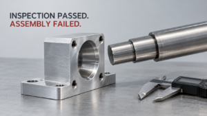
A: For any feature controlling fit, sealing, or assembly, yes — a dimensional tolerance alone doesn’t control roundness, position, or cylindricity, and a part can pass the diameter check while still failing to assemble .
A: Ask for the instrument’s stated uncertainty and compare it to your tolerance band — as a rule of thumb, the measurement uncertainty should be roughly 10 times tighter than the tolerance you’re checking
A: Selective. Reserve tight tolerances for the two or three dimensions that actually determine fit or function, and let the rest follow a general tolerance standard — this is usually the single biggest cost lever in a precision RFQ.