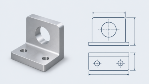
Sheet Metal Bending: How Buyers Can Control Dimensional Errors, Springback, and Cracking
A bent bracket can meet its specified angle and still fail to assemble. A housing can look correct but have distorted mounting holes. A material substitution can preserve nominal force while making a previously reliable bend crack.
These problems often start before production. Drawings specify a radius without confirming the tooling, purchasing documents name an alloy without its temper, or inspection plans check individual flanges without checking the final mounting interface.
For global buyers, the practical solution is to connect the finished requirements with the conditions needed to manufacture them. Material grade, thickness, rolling direction, tooling, forming method, and measurement references all matter.
This guide focuses on press brake bending. Roll bending, hemming, drawing, and other forming operations require their own process assessment. The numerical examples below illustrate specific published conditions or transparent calculations; they are not universal manufacturing limits.
1. Sheet Metal Bending Defects: Separate Dimensional Error, Springback, and Cracking
Sheet metal bending defects refer to unwanted changes in finished geometry or material integrity caused by the interaction of the blank, material, tooling, forming process, and inspection method.
Dimensional error, springback, and cracking can occur together, but they require different corrective actions. Treating every rejected part as an angle problem wastes time and can introduce further defects.
Dimensional errors often begin with the flat pattern
During bending, the outside of the sheet stretches while the inside compresses. The neutral axis separates these regions, and its position influences the developed length needed for the bend.
If the flat pattern uses an unsuitable bend allowance or bend deduction, the finished flange lengths can be incorrect even when the unloaded angle meets the drawing. The research materials identify this mismatch between assumed and actual forming conditions as a central source of dimensional error. [The Fabricator, “K-factors, Y-factors, and press brake bending precision”]
Consider a mounting bracket with two bends and a controlled distance between attachment faces. Checking each angle separately does not establish that the attachment faces are correctly positioned.
The buyer should therefore identify which finished dimensions determine assembly. Manufacturing compensation should support those requirements.
A supplied flat pattern can be useful, but its status must be clear. Is it a reference for quoting, or an approved production file? If the supplier must guarantee both an unvalidated blank and the finished geometry, the requirements may conflict.
Springback changes geometry after unloading
Springback is the elastic recovery that occurs when forming pressure is removed. A part pressed to the desired angle under load may open after it leaves the tools.
SSAB identifies material strength, die opening relative to thickness, punch radius, and the tool combination as relevant influences. Compensation must therefore reflect the actual forming conditions. [SSAB, “Springback”]
This distinction matters during inspection. An angle measured while a part remains constrained does not necessarily describe its free condition.
Overbending can compensate for recovery, but specifying an arbitrary additional angle is not a reliable purchasing rule. The supplier needs sufficient tool clearance and validated settings for the material being processed.
Cracking is a material and process issue
The outer surface of a bend experiences tensile deformation. A tight radius, unsuitable material condition, unfavorable rolling direction, or damaged edge can increase cracking risk. SSAB specifically emphasizes material orientation and edge preparation in bending practice. [SSAB, “Improve workshop operations in bending and forming”]
A larger radius can improve bendability, but it also changes the geometry and developed length. Depending on the tool combination, it may increase springback. Correcting one risk can therefore require adjustments elsewhere.
The commercial opportunity is to avoid treating every rejection as proof that the supplier needs tighter controls. Sometimes the drawing needs a clearer material condition, a more suitable radius, or a different functional datum.
Action recommendation: Classify each critical risk as dimensional error, springback, or cracking, and require a corrective method that addresses its actual cause.
2. Minimum Bend Radius: Specify the Material Condition and the Meaning of the Radius
Minimum bend radius refers to the smallest acceptable inside radius for a defined material and forming condition without unacceptable damage.
The important qualification is “defined condition.” A radius recommendation becomes unreliable when separated from its material grade, product form, thickness, orientation, or tooling requirements.
Distinguish three different radii
Buyers should separate the material’s allowable minimum inside radius, the punch nose radius, and the finished inside radius after unloading.
These values are related, but they are not interchangeable. In air bending, the finished radius depends on the material and die arrangement as well as the punch. A tool marked with a particular radius does not automatically guarantee the same finished radius.
This is why approving a CAD model alone does not validate the manufacturing method.
High-strength steel demonstrates the importance of conditions
SSAB’s published bending guarantees give different requirements within the Strenx product family. The supplied research includes these examples:
| Material and thickness | Minimum finished inside radius | Recommended punch radius |
|---|---|---|
| Strenx 700MC D/E, 3 mm | 2.4 mm, or 0.8t | 3.0 mm, or 1.0t |
| Strenx 700MC D/E, 5 mm | 6.0 mm, or 1.2t | 7.0 mm, or 1.4t |
| Strenx 700 CR, 2 mm | 4.0 mm, or 2.0t | 5.0 mm, or 2.5t |
These figures belong to the manufacturer’s stated bending conditions and product classifications. They should not be applied to every steel with a similar strength designation. [SSAB, “Thickness, flatness and bending guarantees”]
The purchasing implication is straightforward: “high-strength steel” is not a complete specification. Even a strength level does not establish equivalent bendability across different products.
Rolling direction also needs an unambiguous reference. Where orientation matters, show both the rolling direction and bend line on the drawing. Terms such as “with the grain” can cause confusion across companies and languages.
Supplier capability tables have a different purpose
A fabricator’s bending table describes combinations it can manufacture with its available materials and tooling. It is not necessarily a statement of the material’s absolute forming limit.
For example, Protocase lists approximately a 1.016 mm inside radius for 1.016 mm 5052-H32 aluminum. Its listed radius for 3.264 mm 6061-T6 aluminum is approximately 9.271 mm. These are specific entries in its manufacturing table. [Protocase, “Bend Radii & Minimum Bend Sizes”]
The useful lesson is not that either alloy always requires that ratio. It is that alloy, temper, thickness, and available tooling must be considered together.
A stronger material can offer opportunities for structural redesign, but it may also need more space around the bend. A compact enclosure designed around one aluminum condition may not accept another without geometry changes.
Where the radius is noncritical, allowing an approved tooling-compatible alternative can simplify production. Where it controls fit, sealing, or clearance, the finished radius needs explicit verification.
Action recommendation: Specify the exact material and condition, then distinguish mandatory finished radii from radii the supplier may adjust with approval.
3. Hole Clearance and Flange Height: Design Around Deformation and Tool Access
Bend clearance refers to the space required around holes, cutouts, and flanges to form the part without unacceptable distortion, loss of support, or tool interference.
A sheet may be bendable while the complete part remains difficult to manufacture. Local features and bending sequence can determine feasibility as much as material properties.
Define where hole clearance is measured
“Keep the hole away from the bend” is incomplete advice.
The distance might be measured from the hole center to the flat-pattern bend line, from the hole edge to a bend tangent, or from the hole to the formed outside corner. These references cannot be substituted without considering geometry.
Protocase’s table uses its illustrated outside-corner reference and limits the applicability of its hole guidance. The research notes a small-round-hole diameter limit of 9.52 mm, with separate conditions for certain obround slots. [Protocase, “Bend Radii & Minimum Bend Sizes”]
Consequently, a published clearance for a small round hole should not automatically be used for a large opening or rectangular cutout.
The buyer should define both the feature being controlled and the measurement reference. This matters particularly when a mounting hole is positioned from another formed face rather than from the nearest bend.
Minimum flange height is a separate requirement
Hole clearance and minimum flange height describe different constraints.
For 1.016 mm 5052-H32 aluminum, the supplied Protocase table lists approximately 3.810 mm minimum hole distance and 5.080 mm minimum flange size. Their different values show why one should not replace the other. [Protocase, “Bend Radii & Minimum Bend Sizes”]
A short flange may lack adequate support for the selected tool arrangement. It may also be difficult to locate consistently against the backgauge.
The complete shape adds further restrictions. An adjacent wall can obstruct the punch, and a later bend may become inaccessible after an earlier operation.
A supplier’s approval should therefore cover the full bending sequence. Confirming that each bend is possible in isolation is insufficient.
Compare alternatives by total manufacturing effort
When a hole is too close to a bend, possible responses include moving it, changing the local geometry, introducing an appropriate relief, or machining the feature after forming.
Each option changes the cost structure.
Post-bend machining can protect a critical mounting relationship, but it adds handling and fixturing. Moving a noncritical hole may be simpler, provided the assembly permits it. A relief may help local deformation but affect appearance or another function.
The same reasoning applies to a short flange. The right response may be a drawing revision rather than special tooling.
These decisions should be made before production pricing is treated as final. Otherwise, quotations may appear comparable while assuming different manufacturing routes.
The opportunity for buyers is to preserve precision where it matters while giving the supplier flexibility elsewhere. That requires identifying the functional interface, not relaxing requirements indiscriminately.
Action recommendation: Require a full-part manufacturability review covering feature references, hole distortion, flange support, tool interference, and bending sequence.
4. K-Factor and Bend Allowance: Validate the Flat Pattern Through Calculation and Trial Bends
K-factor refers to the ratio between the neutral axis distance from the sheet’s inside surface and the sheet thickness, used when calculating bend allowance.
It is a flat-pattern compensation parameter. It is not a springback correction.
Confusing these functions can lead to repeated adjustments that fix an angle while leaving the finished dimensions incorrect.
Understand the calculation
Using a circular-arc approximation:\[ K=\frac{a}{t} \]
and:\[ BA=\theta(R_i+Kt) \]
Here, \(BA\) is bend allowance, \(a\) is the neutral axis distance from the inside surface, \(t\) is thickness, \(R_i\) is inside radius, and \(\theta\) is the bend rotation in radians.
For a 90-degree bend rotation, \(\theta=\pi/2\). The angle convention must be understood correctly when translating drawing information into the formula. [The Fabricator, “K-factors, Y-factors, and press brake bending precision”]
A default K-factor can provide an initial estimate. It does not prove that the resulting flat pattern will produce an acceptable part.
A calculation shows the dimensional sensitivity
Take an illustrative bend with 2 mm thickness, 2 mm inside radius, and a 90-degree bend rotation.
| Assumed K-factor | Calculated bend allowance |
|---|---|
| 0.33 | 4.178 mm |
| 0.45 | 4.555 mm |
| Difference | 0.377 mm |
These results follow directly from the formula. The selected K-values are comparison inputs, not recommendations for a particular alloy. [Author calculation using The Fabricator bend-allowance formula]
In reviewing this example, I calculated the bend allowance twice while keeping thickness, radius, and angle unchanged. Changing only the assumed K-factor produced a difference of approximately 0.377 mm. My observation from this calculation is that a correct bend angle cannot, by itself, validate the developed length. This is a calculation-based observation, rather than a claim about a physical production trial.
On a part with several bends, compensation errors can affect multiple finished relationships. Their effect depends on bend direction, dimensioning, and the assembly datum structure; they should not simply be added without examining the geometry.
Establish compensation from representative evidence
A useful trial bend uses the intended material grade, condition, thickness, and tooling. The supplier measures the original blank and the finished geometry after unloading.
Those measurements can support an effective K-factor or bend-deduction table for that manufacturing arrangement. The supplied technical research recommends measured test pieces rather than exclusive reliance on default values. [The Fabricator, “K-factors, Y-factors, and press brake bending precision”]
The buyer does not necessarily need to approve every internal machine setting. The important requirement is that manufacturing compensation produces the agreed finished characteristics.
Changes also need proportionate review. A different temper or tool arrangement can make an old compensation table unsuitable. Reusing the same drawing number does not establish that the production conditions remain equivalent.
The opportunity is better transfer between design and manufacturing: maintain clear finished requirements while letting validated process data drive the production flat pattern.
Action recommendation: Approve flat-pattern compensation through representative trial bends, and require reassessment when relevant material or tooling conditions change.
5. Bending Tolerances and Inspection: Control the Finished Assembly Interface
Bending tolerance refers to the permitted variation in formed geometry under specified measurement conditions and relative to defined references.
A tolerance is incomplete if the supplier and buyer measure different features, use different datums, or inspect the part in different states.
Read published tolerances in context
Protocase’s design guidance provides an example of approximately ±0.25 mm per bend and ±1 degree angular tolerance, while warning that variation can accumulate across multiple bends. These figures describe that supplier’s published guidance, not a universal press brake standard. [Protocase, “URC Design Tips,” 2018]
Machine positioning accuracy is also different from finished-part capability. The final result includes the effects of material variation, tooling, geometry, setup, and measurement.
For purchasing, the relevant question is whether the supplier can demonstrate conformity on the actual part.
Long flanges amplify angular variation
Consider an illustrative 100 mm straight flange with a 1-degree angular deviation. Its endpoint’s transverse displacement relative to the nominal direction is:\[ 100\sin(1^\circ)\approx1.75\text{ mm} \]
This is a geometric calculation, not an additional manufacturing tolerance. [Author calculation]
The example explains why a seemingly modest angular variation can matter at a distant mounting location.
A part can satisfy separate angle and flange-length requirements yet still create assembly difficulty if their combined effect is not covered by the inspection plan.
Where fit depends on the mounting hole, control its final position relative to the relevant assembly datums. Do not assume that checking intermediate dimensions establishes the same result.
Define the inspection state
The drawing or inspection agreement should clarify whether dimensions are internal or external, how virtual corners are constructed, and whether the part is inspected freely or in a specified fixture.
Surface treatment also matters to the acceptance definition. Buyers should state whether relevant dimensions are checked before or after coating.
For a long bend, inspection locations should reflect the function. A single angle reading may not adequately describe the entire formed edge.
These are requirements to agree for the part, rather than a new universal checklist imposed on every order.
Use first articles to validate the production route
First-article approval should establish that the proposed material, tooling, sequence, and compensation can produce the functional geometry.
Evidence should address the risks identified during review. For a close-to-bend hole, inspect distortion and final position. For a tight radius, assess the bend condition. For a long flange, verify the mounting interface.
An acceptable sample does not remove the need for production control, but it gives both parties a defined reference.
Avoid tightening every dimension to the same demanding level. A clearance feature and a locating feature serve different purposes. Concentrating inspection and process effort on functional characteristics can improve cost and repeatability together.
Action recommendation: Base acceptance on finished functional features, agreed datums, and a defined inspection state, then validate them through a representative first article.
Foire aux questions
A: No. Suitable radius depends on grade, condition, thickness, orientation, and forming arrangement. A ratio that works for one listed material and tool combination may be unsuitable for another. Use material guidance and supplier validation together.
A: No. K-factor supports bend-allowance calculations for the flat pattern. Springback compensation addresses elastic recovery after unloading. A part can have a correct angle but incorrect flange dimensions, so the two issues need separate evaluation.
A: There is no single distance suitable for every feature and process. Define whether the measurement starts at the hole center or edge and which bend reference it uses. Then confirm the applicable tooling, hole shape, and allowable distortion.
A: It can reduce deformation severity, but it does not remove every cause. Material condition, orientation, and edge damage still matter. A radius change also requires review of clearances, developed length, and springback compensation.
A: Supply one when useful, but identify its status. A reference flat pattern can assist quoting, while a validated production pattern can support manufacturing. Make clear which finished requirements govern acceptance and who maintains the compensation data.
A: Include material identification, drawing revision, relevant finished dimensions and angles, inspection datums, and measurement conditions. Add evidence for the part’s specific risks, such as bend cracking, hole distortion, or mounting-interface position. The report should demonstrate functional conformity.