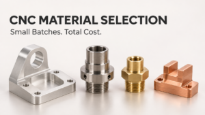
For an order of 10–100 CNC-machined parts, start with the drawing. Identify the directions from which the cutting tool must reach the part, then determine whether those directions can stay fixed during each cut. Finally, compare what it costs to deliver the full batch under each viable machining plan.
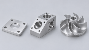
A mounting plate with holes, a pocket, and an underside chamfer might be economical on a three-axis mill. A housing with ports pointing in several directions might benefit from 3+2 machining because the machine can index to each port while the housing stays clamped. A deep, twisting surface might require simultaneous five-axis finishing where the tool and holder need to change orientation along the cut. All three orders could be for 30 pieces. The machining decisions would still be different.
1. Three-Axis CNC Machining for Parts With Straightforward Tool Access
Three-axis CNC machining refers to milling with three linear axes, X, Y, and Z, while the spindle orientation stays fixed relative to the machine during cutting.
Start here for plates, simple brackets, open pockets, and parts whose important features are accessible from one or two directions. Consider an aluminum motor mounting bracket with four clearance holes, a circular locating recess, and an underside counterbore. The shop could machine the holes and locating recess from the top, then flip the bracket to cut the counterbore. If a standard fixture locates the part consistently and the critical dimensions are made together in the first setup, the second operation may add little cost or risk.
The relationship between features matters more than the number of features. Twenty holes drilled from one direction may be routine. One bore that must line up with a feature made after a flip can deserve more attention. In the second case, ask how the part will seat in the fixture, how the shop will reestablish the datum, and how it will verify the relationship between the two features. TiRapid identifies repeated repositioning as a source of alignment error on multi-face work and notes that simpler parts can be economical on three-axis equipment.
A three-axis mill can also cut a curved surface that the tool can reach from a fixed orientation. A ball-end mill can follow a three-dimensional path using X, Y, and Z. For example, an open, shallow curved pocket can often be approached from above. As walls get steeper or the pocket gets deeper, check whether the holder clears the surrounding material and whether the required tool reach makes it difficult to hold the finish. A three-axis plan can be feasible on paper and still take more finishing time than a plan that approaches the same surface from an angle.
The main opportunity is to keep critical features together in a simple operation. If the drawing lets a shop machine the locating recess and mounting pattern from the same side, the underside operation can be evaluated on its own merits. If the supplier proposes several flips to reach related features, ask for a second route. The added quote will show whether reducing handling is worth paying for on this part.
Action: Mark the mating surfaces and critical feature relationships on the drawing, then ask the supplier to identify the setup and locating surfaces for each.
2. 3+2 Machining for Multiple Fixed Cutting Angles
3+2 machining refers to using two rotary axes to set the tool-to-part orientation, then holding that orientation while the three linear axes perform the cut.
This is often the most useful option to quote for multi-face housings, angled ports, sloped faces, and tilted pockets. Picture a manifold with a top sealing face, ports on two side faces, and a bore tilted 30° from the top face normal. Each of those features has a fixed approach direction. An indexed plan can rotate the clamped workpiece to each required orientation, then machine the feature with the rotary axes stationary. A three-axis route could also make the bore with suitable angled workholding. The cost difference depends on the time and fixturing needed to repeat those operations across the batch.
Ask for two counts when comparing routes. The first is the number of indexed positions. The second is the number of physical clampings. A supplier might use four indexed positions while the part stays in the same fixture. It might still need a second physical clamping to finish the face resting on the jaws. Four orientations therefore tell you how many directions the machine will approach from. The clamping count tells you how often the shop will release and locate the workpiece again. Each number helps you assess a different part of the quote.
Indexed machining can also improve tool access. A shop might tilt the workpiece so that a short tool reaches a wall that would otherwise require a long extension. That can make a fixed-angle cut practical. The trade-off appears when the supplier needs many orientations to reach a connected surface. Programming extra positions and blending the boundaries between them can take time. If one of those boundaries lies on a functional or visible surface, ask how the shop will finish and inspect it.
When I compared the published descriptions of 3+2 and simultaneous five-axis machining, I noticed that both could accurately be described as work done on a five-axis machine. The distinction only became clear when I asked what the rotary axes were doing while the tool was cutting. That gave me a more precise way to read a quote. I look for which features are cut at indexed angles and which, if any, require the tool axis to change along the cut.
Action: Request a separate 3+2 quote for a multi-face part and ask for the indexed orientations, physical clampings, and operation used to finish the clamped face.
3. Simultaneous Five-Axis Machining for Cuts That Need Changing Tool Orientation
Simultaneous five-axis machining refers to coordinated linear and rotary motion that can change the tool-axis direction relative to the workpiece during a cut.
This approach makes sense when the tool or holder needs to keep changing angle to reach the required geometry or maintain suitable cutting contact. Imagine a curved channel with a wall that twists as it gets deeper. From one fixed angle, the tool may reach the entry but the holder may interfere farther along the channel. From another angle, the holder may clear the deeper section but have poor access near the entry. Coordinated rotary motion can let the shop vary the orientation along that section of the path.
A part can have both simple and demanding areas. Take a contoured component with a flat mounting face, four threaded holes, and a recessed surface with a changing wall angle. The flat face and threads may use ordinary fixed-angle paths. The recessed surface may need simultaneous motion for finishing. Ask which operations fall into each category. The supplier can then explain whether the simultaneous work is limited to one finishing pass or whether it affects a substantial share of the cycle.
There is also a difference between reaching a surface and meeting its acceptance criteria. A supplier might reach a surface from two fixed orientations and blend the passes. That may work well for a clearance surface. On a sealing surface or a visible transition, the join between passes may matter. Put the relevant profile or surface finish requirement on the drawing and ask the supplier to explain how its proposed route meets it. Five-axis tool motion gives the programmer more ways to approach the cut. The inspection plan tells you how the shop will demonstrate that the finished part meets the requirement.
Allow for the extra preparation that can come with coordinated motion. The shop may need to program and verify clearance for the cutter, holder, fixture, and workpiece through the entire path. On a small order, the preparation matters because it is spread over fewer pieces. Where the path solves a clear access or finish issue, that effort has a purpose you can evaluate. A marked-up screenshot of the relevant surface often gives procurement and engineering enough information to discuss the trade-off with the supplier.
Action: Ask the supplier to mark every region quoted for simultaneous cutting and explain the access, interference, or surface requirement that drives the choice.
4. Batch Cost Comparison for Orders of 10 to 100 Pieces
Batch cost comparison refers to evaluating the total price of producing and verifying a specified quantity of acceptable parts under each feasible machining plan.
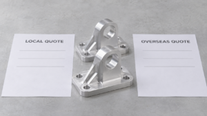
For each route, ask what is paid once for the order and what repeats on each part. The first group can include programming, process preparation, dedicated workholding, and first-article verification. The second can include material, machining, loading, re-clamping, deburring, and routine inspection. Keep the same drawing revision, material, finish, inspection scope, and delivery terms across quotes. Where the supplier charges freight or packaging separately, bring both quotes to the same delivery basis before comparing the totals.
Use this calculation for comparison: batch cost = upfront preparation and verification + quantity × recurring cost per part. The calculation is a purchasing model. A supplier may build setup into the piece price or apply quantity-specific pricing, so use the actual quoted totals to make the award.
Consider an illustrative comparison for a part that both routes can produce to the same drawing. Assume three-axis machining costs $180 upfront and $32 per piece. Assume 3+2 machining costs $420 upfront and $24 per piece because the indexed route reduces handling on every unit. These inputs are hypothetical and represent one part and one set of assumptions.
| Batch quantity | Three-axis batch cost | 3+2 batch cost | Lower cost in this example |
|---|---|---|---|
| 10 | $500 | $660 | Three-axis by $160 |
| 30 | $1,140 | $1,140 | Equal |
| 50 | $1,780 | $1,620 | 3+2 by $160 |
| 100 | $3,380 | $2,820 | 3+2 by $560 |
Here, the indexed route recovers its additional $240 of preparation at 30 pieces because it saves $8 on each part. If the per-part saving drops to $4, the break-even quantity moves to 60. If the indexed route has both higher upfront and higher recurring costs, there is no break-even under this model. It may still be a valid choice if it delivers a requirement that the cheaper route cannot reliably meet. The table assumes comparable quality, yield, and delivery terms.
Near 10 pieces, ask exactly what the first order pays for. A complex part can still be cheaper to index if the three-axis alternative requires several dedicated fixtures. Near 100 pieces, ask how often each unit is loaded, flipped, aligned, and checked. If indexing saves two minutes of repeated handling per part, that amounts to 200 minutes across 100 pieces. That arithmetic shows why a shop should consider handling alongside spindle time. It does not establish the cash saving, which depends on how the shop staffs and schedules the operation.
For repeat purchases, request a separate reorder price. A supplier may be able to reuse the program and fixture if the revision and material stay the same. Machine setup and some verification work can still recur with each release. Clarify what the first order pays for and what repeats on a reorder before using first-order piece prices to estimate annual spending.
Action: Request comparable totals at your expected order quantities, such as 10, 50, and 100 pieces, and ask what the supplier would charge for an unchanged reorder.
5. RFQ Review for Tool Access, Workholding, and Inspection
RFQ review refers to checking a supplier’s proposed machining route against the drawing, acceptance criteria, batch quantity, and commercial scope before issuing a purchase order.
Send a 3D model and a controlled drawing. Use the model to show geometry and the drawing to communicate material, revision, datums, tolerances, finish, and inspection requirements. Call out the dimensions that affect assembly. For example, if an angled port must align with a bore on a neighboring face, identify the datum relationship that governs alignment. The supplier can then decide whether to machine those features in one clamping or transfer the datum through another setup. Ask for the corresponding measurement method on the first article.
Five questions are enough to make most quotes comparable.
- Which routes can meet the drawing? Ask the supplier to consider three-axis, 3+2, and simultaneous five-axis machining where applicable, and identify the feature or tolerance that rules out a route.
- How many physical clampings are required? Ask what locates the part in each clamping, whether dedicated fixtures are needed, and when the clamped face is finished.
- Which regions require simultaneous motion? Ask for a marked view of the relevant area and the reason the tool-axis direction must change during the cut.
- How is the price built? Ask which programming, fixture, and first-article charges are upfront and which machining, handling, and inspection costs repeat.
- How will critical dimensions across faces be verified? Ask which datums the supplier uses, how it measures the features, and what results will appear on the inspection report.
Read the answers against the part. If a housing has three angled holes that each follow a straight axis, the supplier should be able to describe the fixed positions or fixtures used to drill them. If it proposes five-axis finishing for a connected contour, it should be able to show where changing orientation helps. If it quotes one clamping, verify where it grips the blank and whether the drawing requires finishing that region after release. These are details you can compare even when suppliers use different machines.
Leave room for the supplier to suggest a simpler route. If a feature drives the quote and engineering has flexibility, ask for a priced design option. Moving an angled hole to a face already accessible in the primary setup, for instance, could remove a workholding operation if the hole’s function allows it. Keep the original drawing as the basis of the main quote and ask the supplier to state the effect of the proposed change on price and lead time. Engineering can then decide whether to release a revision.
Action: Send the five questions with the RFQ and resolve any difference in inspection scope or critical dimensions before comparing final batch prices.
Frequently Asked Questions
A: There is no universal quantity. First establish which routes can make the geometry to specification. Then compare upfront costs and recurring costs at the quantities you expect to order. For one part the switch may make sense at 10 pieces. For another, three-axis may stay economical at 100.
A: If each hole follows a straight direction that the tool can reach with sufficient clearance, evaluate 3+2 or angled fixtures. Check whether the drill and holder can clear nearby walls and clamps at each orientation.
A: Yes. A three-axis mill can follow a curved path in X, Y, and Z when the tool can reach the surface from its fixed orientation. The practical limits are tool and holder clearance, tool reach, and the required surface finish.
A: Yes. A three-axis mill can follow a curved path in X, Y, and Z when the tool can reach the surface from its fixed orientation. The practical limits are tool and holder clearance, tool reach, and the required surface finish.
A: Yes, on equipment and controls that support both modes. The shop can index for fixed-angle work such as drilling and use simultaneous motion on a specific contour that benefits from changing the tool orientation.
A: Confirm the same drawing revision, material, finish, inspection scope, and delivery terms. Then compare the batch totals, the number of physical clampings, and the inspection plan for critical features made on different faces.