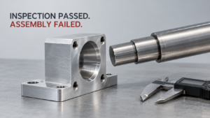
A shipment arrives with an approved dimensional report. Incoming inspection finds no obvious problem. Then production starts, and the parts bind, bolt holes fail to align, or a sealed connection leaks.
The immediate reaction is usually to demand tighter inspection. Sometimes that is necessary. However, more inspection cannot repair an incomplete interface definition, and a longer report cannot prove a function that nobody specified.
For global hardware buyers, the practical objective is to connect assembly requirements with drawings, manufacturing controls, inspection evidence, and shipment approval. Each document should answer a different question while referring to the same controlled requirements.
This article explains how to build that connection without applying expensive automotive or aerospace procedures to every ordinary component. Numerical examples are illustrative engineering requirements from the supplied research, not universal acceptance limits.
1. Separate Part Conformity from Assembly Performance
Assembly conformity refers to the ability of specified mating components to assemble and perform under defined conditions, while part conformity concerns whether an individual component meets its complete technical requirements.
That distinction matters because “passed inspection but failed assembly” can describe two different failures.
In the first case, the component actually satisfies every applicable requirement. The assembly still fails because the design, tolerance allocation, interface definition, or operating assumptions are incomplete.
In the second case, the report says the component passed, but the evidence does not establish complete conformity. Perhaps inspection omitted a drawing note, used the wrong datum alignment, or measured the component before its final surface treatment.
These cases require different corrective actions. Treating both as supplier machining errors encourages disputes and leaves the actual cause unresolved.
Consider the illustrative fit below:
| Feature | Specified final size |
|---|---|
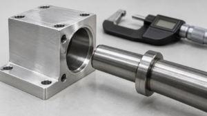
| Bore diameter | 10.020–10.035 mm |
| Shaft diameter | 9.995–10.005 mm |
| Minimum diametral clearance | 0.015 mm |
| Maximum diametral clearance | 0.040 mm |
The clearance calculations are straightforward: minimum bore minus maximum shaft, and maximum bore minus minimum shaft. These values establish a size-based clearance range; they do not establish acceptable alignment, form, surface condition, or operating performance. [Supplied Research Materials—Illustrative Fit Example]
I checked the clearance calculation in the supplied research myself: 10.020 − 10.005 gives 0.015 mm, and 10.035 − 9.995 gives 0.040 mm. My observation from this calculation is limited but useful: the stated size limits provide positive diametral clearance. They do not demonstrate that a long shaft will pass through misaligned supports or that a finished assembly will rotate freely. This is a calculation review, not a physical assembly experiment.
The purchasing mistake is to turn a narrow result into a broad promise. “The diameter is within tolerance” becomes “the shaft will fit,” even though the second statement requires additional evidence.
Buyers should therefore define responsibility before production. The buyer normally controls the system design and interface requirements. The supplier controls conformity to the agreed manufacturing requirements. Feasibility review, interface clarification, and assembly validation may require joint work.
A supplier should identify an evident manufacturing or inspection problem during quotation. Nevertheless, an undefined system requirement cannot become a measurable acceptance criterion merely because the purchase order says “guarantee assembly.”
There is also an opportunity here. An assembly problem does not always require tighter tolerances. Better locating features, a revised datum scheme, or a controlled assembly sequence may solve the problem with less manufacturing cost.
Action recommendation: Before assigning corrective action, determine whether the failure comes from incomplete requirements or failure to meet existing requirements, and record the evidence supporting that decision.
2. Turn Assembly Needs into Controlled RFQ and Drawing Requirements
An assembly interface specification refers to the controlled definition of mating features, functional conditions, acceptance criteria, and responsibilities needed to make separate components work together.
“Manufacture according to drawing” is useful only when the drawing and its referenced specifications adequately define the product.
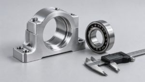
A buyer requesting a bearing support, for example, should identify more than its bore diameter. The supplier may also need to understand the locating face, mounting pattern, mating shaft, bearing arrangement, surface treatment, and relevant operating conditions.
This does not mean placing the complete machine design in every RFQ. It means supplying enough controlled interface information to identify risks before quotation.
Keep the documents focused:
| Document | Primary purpose | Essential content |
|---|---|---|
| RFQ technical attachment | Establish feasibility and quotation scope | Function, mating interfaces, critical features, validation needs, assumptions |
| Drawing or controlled model | Define the product | Dimensions, datums, geometry, material, finish, edge requirements |
| Purchase order and quality agreement | Define evidence and release controls | Revisions, inspection scope, approval stages, changes, traceability |
Assign each important requirement a unique source. Other documents should reference that source rather than repeat independently maintained values.
For example, identify the locating bore as AC-01. Use that identifier in the drawing, inspection plan, measurement report, and assembly validation record. A reviewer can then follow one characteristic from requirement to result.
The supplied research proposes this feature-based linkage as a practical purchasing tool. It reflects the coordinated use of planning, risk analysis, measurement, and production controls without claiming that the proposed matrix is an official standard form. [Supplied Research Materials—Assembly Conformity Matrix]
Specify mating component numbers and revisions. Otherwise, a supplier may validate against an obsolete sample while the buyer assembles against a changed interface.
State whether production requires interchangeable assembly or approved selective matching. Selective matching can be a valid design choice, but it requires grouping rules, identification, and replacement planning. Unrecorded matching during sample approval conceals variation.
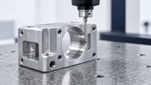
Datums also need functional logic. If the component locates against a mounting face and locating pins during assembly, the inspection alignment should represent the drawing’s intended constraints. A convenient best-fit alignment may answer a different geometric question.
The research identifies ASME Y14.5 and the ISO geometrical product specification framework as relevant references. Buyers should specify the applicable system and contractual edition rather than assume that similar symbols establish identical interpretation. [ASME Y14 Standards; Supplied Research Materials]
Avoid tightening every dimension as a substitute for interface analysis. Excessively narrow tolerances increase manufacturing and inspection demands while potentially leaving the decisive geometric relationship uncontrolled.
The commercial benefit of a clear RFQ is better quotation comparability. Suppliers can price the same final-state requirements, tooling, and validation work. A cheaper quotation based on pre-treatment measurements is not equivalent to one covering finished-part verification.
Action recommendation: Attach an interface matrix to the RFQ showing each critical feature, mating revision, requirement source, final condition, verification method, and approval owner.
3. Verify the Finished Part with an Agreed Measurement Method
Final-state verification refers to checking the component after the operations that determine its delivered dimensions, geometry, surface condition, and cleanliness.
A machined component can change after its first dimensional inspection. Heat treatment, coating, cleaning, deburring, straightening, and handling may affect the interface that eventually reaches the assembly line.
The purchase specification should identify which dimensions are process controls and which apply to the delivered product. A pre-coating measurement can support process control without proving final acceptance.
For critical interfaces, agree how the supplier will measure the finished condition. Include access limitations: a feature that is easy to probe before assembly or treatment may become difficult to evaluate afterward.
Measurement conditions matter as well. A thin bracket can behave differently when freely supported and when clamped. Different support points, clamp forces, or measurement forces can produce different results.
Record the required state, fixture arrangement, temperature conditions, and relevant evaluation settings. Where borderline results are likely, agree the conformity decision rule and treatment of measurement uncertainty. The supplied research identifies ISO 14253-1 as the relevant framework for this issue. [ISO 14253-1; Supplied Research Materials]
Do not confuse instrument resolution with demonstrated measurement suitability. A display showing additional decimal places does not establish repeatability, reproducibility, or adequate uncertainty.
A useful correlation exercise has both parties measure identified samples using their proposed methods. Include samples representing meaningful variation, and investigate disagreements before those methods control shipment release.
Burrs and cleanliness require similarly explicit treatment. “Deburr all edges” gives limited guidance for an internal cross-hole, a sealing edge, or a thin feature that cannot tolerate aggressive edge removal.
An illustrative requirement in the research limits protruding material on designated non-sealing edges to 0.03 mm under 10× observation. That is a proposed application-specific criterion, not an industry-wide burr allowance. [Supplied Research Materials—Illustrative Acceptance Criteria]
The important work is defining the location, permitted condition, inspection access, and method. An external visual check does not establish the condition of an inaccessible internal intersection.
Cleanliness needs a separate specification. ISO 16232 addresses particulate cleanliness inspection and reporting for road-vehicle components and systems, but it does not assign universal cleanliness limits to individual products. It also excludes film contamination such as oil and grease from its scope. [ISO 16232] Cleanliness of components and systems
For illustration, the research proposes a maximum metallic particle length of 200 μm and no more than five metallic particles larger than 100 μm per component. These figures require application-specific justification and an agreed extraction and analysis procedure. [Supplied Research Materials—Illustrative Cleanliness Criteria]
The opportunity is to replace arguments about “clean enough” or “measures correctly” with reproducible evidence. That makes supplier comparisons and root-cause analysis substantially more useful.
Action recommendation: Approve a finished-part verification plan covering process state, fixturing, measurement correlation, decision rules, burr locations, cleanliness methods, and protective packaging.
4. Combine First-Article Evidence with Functional Validation
Functional validation refers to testing whether representative production components meet defined assembly and operating criteria using controlled mating parts, fixtures, and test conditions.
Dimensional inspection, functional gauges, and assembly trials provide different evidence. A strong approval process uses each where it answers a relevant question.
A functional gauge may check a defined geometric boundary or simultaneous engagement condition. Passing it does not automatically establish material properties, cleanliness, sealing performance, or every drawing requirement.
An assembly trial demonstrates behavior against the particular mating parts and conditions used. Its value depends on whether those conditions represent the intended production interface.
A supplier’s convenient mating sample may be too generous. Conversely, a damaged or incorrectly identified buyer sample may create misleading failures. Control the mating parts, their revisions, and their verified condition.
The research offers an illustrative trial plan: take five components from each independent production stream and test them against three approved interface conditions, producing 15 assembly trials per stream. Those conditions must come from interface analysis rather than arbitrary “small, medium, and large” labels. [Supplied Research Materials—Illustrative Trial Coverage]
Even zero failures in that exercise would establish only the observed trial result. It would not prove a very low production failure rate or cover untested manufacturing conditions.
Define measurable functional criteria. Depending on the product, these could include insertion force, running torque, press force versus displacement, fastener engagement, positional alignment, or leakage.
For example, the research proposes an illustrative maximum insertion force of 50 N at 23 ± 2 °C. Without a specified insertion speed, lubrication condition, alignment, and insertion depth, that force limit remains incomplete. [Supplied Research Materials—Illustrative Insertion Test]
Record initial failures. If a component passes after filing, lubrication changes, repeated cycling, or selective matching, retain that sequence in the report. Otherwise, the approval record hides the process actually needed to obtain success.
First-article inspection adds another layer. It should connect applicable product characteristics with actual results from the intended production route, including relevant materials and outside processes.
IAQG describes 9102 as a standardized first-article inspection framework developed primarily for aviation, space, and defense, while allowing use in other sectors where appropriate. Its purpose does not make the aerospace format mandatory for every industrial purchase. [IAQG 9102] IAQG
A general industrial buyer can use characteristic-by-characteristic verification without requiring unnecessary paperwork. Automotive purchases may require PPAP where the customer or contract calls for it.
Separate sample approval from production shipment authorization. A successful prototype does not qualify an untested coating supplier, alternate fixture, or different manufacturing location.
Action recommendation: Approve production only after representative first-article evidence and controlled functional tests demonstrate the specified interfaces without unapproved adjustment or selective matching.
5. Maintain Assembly Performance through Production and Change Control
Production assurance refers to the continuing controls that keep approved requirements, manufacturing conditions, verification methods, and traceability effective after initial approval.
A successful first article is a starting point. Tool wear, fixture damage, process transfers, coating variation, and inspection changes can alter later deliveries.
The control plan should connect each critical characteristic with its manufacturing operation, verification frequency, record, and reaction rule. If a result fails, operators should know what to stop, what to isolate, and who can authorize release.
AIAG groups APQP, Control Plan, PPAP, FMEA, MSA, and SPC within its Quality Core Tools framework. For buyers, the useful principle is their connection: identified risks should influence controls, and measurement evidence should support production decisions. [AIAG Quality Core Tools] AIAG
Capability indices can help evaluate variation, but their meaning depends on the study. Buyers need to understand the data source, time coverage, production streams, measurement suitability, and statistical assumptions.
The research gives illustrative targets of initial Ppk ≥ 1.67 and stable-production Cpk ≥ 1.33. These are possible contractual criteria, not thresholds that automatically apply across industries. [Supplied Research Materials—Illustrative Capability Targets]
A combined result can also conceal differences between machines or cavities. Review meaningful production streams separately before accepting an overall summary.
When capability is inadequate, temporary screening may protect the customer only if the screening method reliably detects the relevant defect. It cannot compensate for an inspection method that misses the failure mechanism.
Change control should identify changes requiring advance approval. Relevant examples include material source, manufacturing location, fixture design, special-process supplier, cleaning route, and measurement method.
Distinguish substantive changes from routine adjustments inside an approved process window. An approval system that captures every ordinary adjustment can become too slow to use effectively.
The research proposes 60 calendar days’ notice for planned changes as an illustrative purchasing condition. The appropriate period depends on qualification work and contractual needs. [Supplied Research Materials—Illustrative Change Requirements]
Temporary deviations should identify affected parts, revisions, quantities or lots, and expiry conditions. A concession for one shipment should not silently become a permanent drawing change.
Traceability should connect delivered lots with relevant material, manufacturing, treatment, inspection, and change records. Preserve those relationships through splitting, rework, sorting, and repackaging.
This creates a commercial opportunity during a problem: evidence can narrow containment to affected products instead of forcing a blanket quarantine of unrelated inventory.
Before release, close the specification, measurement, production-validation, and continuing-control questions. The objective is a usable evidence chain that shows why the delivered parts should assemble consistently.
Action recommendation: Require a production control plan with explicit containment rules, change triggers, approval authority, and lot links that remain intact through rework and delivery.
Frequently Asked Questions
A: No. Establish whether the parts meet the complete technical definition, including notes, referenced specifications, geometry, material, and final condition. If they do, investigate interface design and operating assumptions. If inspection omitted or misapplied a requirement, investigate that conformity failure. Responsibility should follow the evidence and agreed scope.
A: Only when engineering analysis shows that variation in those dimensions causes the problem. Misalignment, burrs, coating buildup, or an incorrect locating scheme may require different controls. Tightening an unrelated dimension adds cost while leaving the failure mechanism active.
A: It can replace specified checks only when its coverage and use have been approved. Document what it verifies and what remains outside its scope. A gauge that checks simultaneous hole engagement does not establish hardness, cleanliness, or the condition of an unrelated sealing surface.
A: No. It provides a framework for particulate cleanliness inspection and reporting within its scope. Product-specific limits must reflect the component and system. The extraction procedure, inspection area, particle classification, and reporting basis must also be agreed.
A: No. Apply the process required by the contract, customer, and industry. General industrial purchases can use a focused approval package containing controlled requirements, actual inspection results, process evidence, and relevant functional validation. Formal sector requirements should be invoked deliberately.
A: Add an assembly interface matrix. Identify the critical feature, mating revision, functional consequence, requirement source, final process state, verification method, production control, and responsible approver. Leave unresolved items visible as quotation assumptions or open technical questions rather than treating them as accepted supplier commitments.