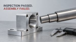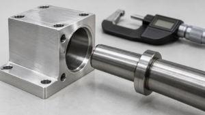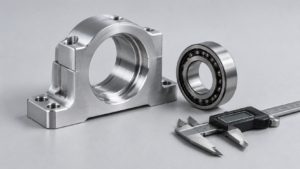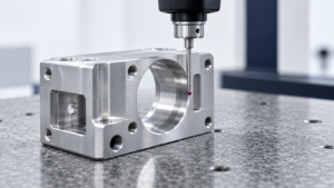
A supplier sends a dimensional report marked PASS. The shipment arrives. On the assembly line, a bolt pattern does not align, a bearing stops halfway into its housing, or a threaded connection binds. The immediate argument is predictable: the supplier points to the report; the buyer points to the failed assembly. Neither document alone settles what happened.
There are three separate claims to test. First, did the inspected characteristics pass the checks shown in the report? Second, does the part meet every applicable requirement in the agreed drawing and purchase specification? Third, does the assembled system work under its intended conditions? A positive answer to the first question proves neither the second nor the third. The UK National Physical Laboratory (NPL) notes that coordinate measuring machine (CMM) results depend on such choices as point selection, alignment, temperature, surface condition, geometry, and interpretation of the drawing [NPL, CMM Measurement Strategies GPG41].
For a buyer, the useful response is a short evidence trail: freeze the drawing revision, identify the failed interface, inspect the actual failed parts, then test the proposed cause against the assembly. Here is how to do that without declaring a supplier at fault before the measurements justify it.
1. An Inspection PASS Is a Statement About a Measurement Plan
An inspection PASS refers to the result of specified measurements evaluated against specified acceptance limits; it does not automatically certify every feature or the completed assembly.
Read a report as a record of what someone checked. A row showing that a hole diameter falls inside tolerance does not tell you whether the hole is in the right place relative to the assembly datums. A measured shaft diameter may be acceptable at one section while the shaft’s form changes along its length. A single surface-roughness result may be useful, but it cannot represent every local defect on a sealing track. These are different measurands, and each needs an appropriate method [NPL, CMM Measurement Strategies GPG41; NPL, Good Practice Guide 130].
Start with the drawing. Which revision governed the order? Does it include a general-tolerance note, referenced standard, position or form requirement, finish, thread designation, and inspection agreement? Compare that complete list with the report line by line. A missing characteristic is not a passing characteristic. Nor can an inspector silently replace a functional datum with a best-fit alignment that makes an isolated feature look better; whether best fit is appropriate depends on the drawing’s evaluation rules [NPL, CMM Measurement Strategies GPG41; ZEISS, Geometrical Tolerancing Reference].
There are two importantly different outcomes. In the first, the part meets the complete, correctly interpreted drawing, but the drawing allows an assembly failure. That points toward a design, tolerance-stack, or functional-specification gap. In the second, the report covers only selected dimensions or uses an unsuitable method, while the part actually violates an existing requirement. That points toward an inspection or manufacturing problem. A third possibility is that damage, contamination, fixturing, or use changed the part between inspection and assembly. Do not collapse these into a generic claim that “the part passed inspection but is bad.”
Action: Mark every assembly-critical interface on the drawing and require the inspection report to name its datum, measured characteristic, method, and acceptance rule.
2. A Correct Part Can Still Be a Bad Fit in a Tolerance Stack
A tolerance stack refers to the combined variation of several mating dimensions or geometric relationships that determines a final gap, alignment, or interference.
A single part is not an assembly. An enclosure cover, locating pins, bearing, seal, and fasteners each contribute variation. Parts can be within their individual limits and still form an unacceptable combination if the permitted limits were never checked together. Reata Engineering recommends evaluating tolerances across mating components rather than treating each item independently [Reata Engineering, How to Avoid Tolerance Stacking Problems When Designing Mating Parts].
Take a simple illustrative example, not a published production case. A slot may be specified as 10.00 ±0.10 mm and its mating tab as 9.95 ±0.10 mm. At nominal dimensions, clearance is 0.05 mm. At the worst permitted combination, the slot is 9.90 mm and the tab is 10.05 mm, creating 0.15 mm of interference. Both parts can pass their separate dimensional checks. The calculation is merely 9.90 minus 10.05; it is not a universal recommendation for slot or tab tolerance. Add coating, burrs, thermal expansion, or positional error and the functional result can shift further.
The same logic applies to bolt patterns, stacked brackets, and bearings. A shaft and housing may each meet their size callouts while the selected fit does not suit the load, temperature, mounting method, or bearing supplier’s specifications. Form can matter as well: a small set of diameter readings need not capture local lobing or taper. NPL advises changing sampling locations and considering uncertainty when form affects the measurement [NPL, Good Practice Guide 130]. A peer-reviewed study on assembled spherical roller bearings examined how roundness errors stack and affect rotor vibration; it supports the importance of mounting geometry, but it is not evidence that any particular buyer received an incorrectly inspected bearing seat [Aalto University repository, Roundness Error Stacking in Assembled Spherical Roller Bearings].
JLC described a bearing that would not seat fully because a stepped hole was too small and a mating cylinder too large. Its account says the customer supplied a 3D model without a 2D tolerance for the bearing interface, so the factory used a general ±0.1 mm machining tolerance [JLC, CNC Drawing Problem Analysis]. The case illustrates an underdefined interface; it does not publish original inspection records or independent remeasurement proving that all requirements passed.
Before approving production, write down the assembly condition in plain terms: which surfaces locate the parts, how much clearance or interference is acceptable, where a coating is applied, and what temperature or load matters. Then convert those conditions into controlled dimensions and a verification method. This creates an opportunity to spend precision only where it improves function. Tightening every dimension raises cost without necessarily fixing the actual stack.
Action: Calculate the minimum and maximum functional fit from the allowed limits of all mating parts before issuing the purchase order.
3. Five Failure Modes That a Short Dimensional Report Can Miss
A failure mode refers to the specific way a part or assembly stops performing its intended function, such as misalignment, interference, thread binding, leakage, or jamming.
The following five modes are useful investigation paths, not a fixed inspection recipe for every order. Each starts with an observable assembly symptom and asks whether the design allowed it, the inspection missed a specified requirement, or the part changed after inspection.
Bolt holes do not line up. The report may list acceptable diameters and center-to-center distances, while the whole hole pattern is displaced or rotated relative to the actual locating faces. If the drawing already specified position and datums, check whether the supplier evaluated that requirement as written. If it did not, decide whether the assembly needs a pattern-position requirement or a functional gauge. A part’s local measurements and its location in a real fixture are distinct questions [NPL, CMM Measurement Strategies GPG41; ZEISS, Geometrical Tolerancing Reference].
A bearing, bushing, or shaft binds. A diameter at one cross-section may be in tolerance while form, taper, edge damage, temperature, or the chosen fit creates trouble. Equally, all controlled characteristics could pass while the design’s chosen interference is unsuitable. Measure at multiple sections, inspect the relevant form, identify the bearing and mating-part requirements, and reproduce the installation process before assigning cause. A published bearing-roundness study establishes that mounting geometry can affect assembled behavior; it does not prescribe one universal bearing-seat tolerance [Aalto University repository, Roundness Error Stacking in Assembled Spherical Roller Bearings; NPL, Good Practice Guide 130].
A thread starts but will not run to depth. A reported pitch diameter alone may not settle pitch, lead, flank form, incomplete threads, burrs, and usable engagement length. Vermont Gage explains that a GO thread plug gauge checks the cumulative effect of multiple thread elements through the full specified length; its NO-GO counterpart serves a different purpose [Vermont Gage, Internal Part Thread Inspection]. Select gauges for the actual specified thread and inspect the mating connection where needed. JLC’s public account includes a nonstandard male/female thread mismatch and a separate example in which an intended M4×0.5 thread was indicated only as M4 [JLC, CNC Drawing Problem Analysis]. Those are different possible failures: one may involve execution or definition of a special form; the other involves an omitted pitch. Do not infer either root cause from a photograph of a jammed thread.
A sealing interface leaks. An acceptable Ra result does not guarantee a leak-free joint. The seal material, compression, groove geometry, local damage, and direction of machining marks can all affect performance. Greene Tweed’s published seal-leakage experiments compared different machining patterns and found that texture direction could have a stronger effect than a single roughness number under the tested conditions [Greene Tweed, Methods of Evaluation of Seal Leakage]. That is evidence about the tested seal geometry and conditions, not a universal leakage threshold. A separate reported pump case traced leakage in two EUROFLO EU80/20 MBC pumps to rust particles that damaged mechanical-seal faces; the case did not publish a failed factory dimensional report [Winston Engineering, Resolving Mechanical Seal Leakage Caused by Rust and Abrasive Particles]. Check interface leakage against the specified fluid, pressure, assembly condition, and allowable rate; also rule out contamination and material permeation before blaming machining.
A multi-part mechanism jams. A slide may move freely as a loose component but bind once several frames, spacers, rails, and fasteners are combined. Separate passes for each part do not measure the resulting path. Establish the functional datum sequence, calculate accumulated variation, and inspect the assembled mechanism at its travel extremes. Reata’s mating-part guidance supports the stack-up principle; the exact test and acceptance limit must still be set by the application’s design team [Reata Engineering, How to Avoid Tolerance Stacking Problems When Designing Mating Parts].
Action: Record the exact failed interface and pair its targeted measurement with a controlled physical fit or function test.
4. Investigate the Dispute With Drawing, Measurement, and Function Evidence
A root-cause investigation refers to a controlled comparison between the agreed specification, the condition of the failed parts, and the assembly behavior the proposed defect is supposed to explain.
Next establish the contract baseline. Put the purchase order, approved drawing revision, 3D model, referenced standards, approved deviations, and inspection plan in one package. If the PDF and model differ, identify the agreed precedence before changing dimensions. A dispute over a supposed “missing” positional tolerance cannot be settled by looking only at one cropped drawing view; general notes and invoked standards may apply. ZEISS’s reference separates form, orientation, location, and runout controls and discusses general versus individually specified requirements [ZEISS, Geometrical Tolerancing Reference].
Then establish measurement equivalence. Ask the supplier for raw CMM points or gauge records, not merely a color-coded PASS table. Confirm probe strategy, datum establishment, alignment, software evaluation, temperature, surface condition, calibration status, and the exact parts measured. If the customer gets a different number, compare whether both laboratories measured the same feature under the same definition. At a tolerance boundary, document measurement uncertainty and the agreed decision rule; two different reported values do not automatically tell you which party is right [NPL, CMM Measurement Strategies GPG41; NPL, Good Practice Guide 130; NPL, Good Practice Guide 42].
Finally test causation. If a hole pattern appears displaced, fixture it on the real datums and demonstrate the bolt clash. If a shaft seems out of round, map form at relevant sections and correlate it with the contact or vibration problem. If a seal leaks, inspect the sealing track and run the agreed leakage procedure while distinguishing interface leakage from other sources. If a tolerance stack is the hypothesis, insert actual measured dimensions into the calculation and compare the predicted interference with the physical location of the jam [NPL, CMM Measurement Strategies GPG41; Greene Tweed, Methods of Evaluation of Seal Leakage; Reata Engineering, How to Avoid Tolerance Stacking Problems When Designing Mating Parts].
A convincing correction does more than remove a visible deviation. It shows that the deviation occurred at the failed interface, could produce the observed symptom, and that changing it restores function under a repeatable test. If the failed part actually conforms to the complete drawing, the correction may be a revised design, clearance requirement, or acceptance test. If the drawing already controlled the feature and inspection missed it, the correction belongs in manufacturing and measurement control. If contamination appeared after shipment, packaging, handling, and the assembly environment may deserve attention. Assign corrective action to the proven mechanism rather than to the party with the weaker-looking PDF.
Author observation to insert before publication: “I personally [describe the real part and assembly], compared [the exact inspection result] with [the physical fit or independent measurement], and observed [what actually happened]. The case showed [the narrow conclusion supported by that observation].” This paragraph requires your own documented experience; the supplied research contains no first-person experiment that can truthfully be attributed to you.
Action: Require any proposed root cause to connect a documented requirement, an observed measurement, and a reproducible assembly result.
5. Turn the Finding Into a Better RFQ and Acceptance Plan
An acceptance plan refers to the agreed set of drawings, inspections, functional tests, records, and decision rules used to release parts for production and receipt.
Most buyers can improve reliability without asking a machine shop to measure everything. Start by defining the interfaces that actually determine function: a bearing seat, a seal land, a pin pattern, a threaded engagement, or a sliding clearance. For each, identify the mating component, the datum established during assembly, the governing requirement, and the test that will show whether the function is achieved. A specification that says “precision machined” communicates none of these things.
An effective RFQ package can include the controlled 2D drawing and 3D model, revision, material and finish, critical dimensions, mating drawings when appropriate, expected quantities, inspection sampling, and any assembly or leak test. It should also state what happens after a revision, which dimensions require first-article evidence, and how near-limit results will be judged. NPL’s measurement guidance supports aligning the measurement strategy with drawing requirements and evaluating uncertainty; it does not dictate one inspection frequency for every buyer [NPL, CMM Measurement Strategies GPG41; NPL, Good Practice Guide 42].
For a bolted mounting plate, specify the hole pattern relative to surfaces that locate it in service and agree whether a functional fixture is useful. For a bearing interface, use the bearing maker’s fit guidance and determine the necessary size, form, and temperature conditions rather than copying a tolerance from another assembly. For a nonstandard thread, provide a complete profile definition and a mating sample or jointly approved gauge where appropriate. For a seal, define the groove and contact surface together with the operating medium, pressure, assembly method, and leakage acceptance criterion. These details turn an inspection report into evidence of the right question [Vermont Gage, Internal Part Thread Inspection; Greene Tweed, Methods of Evaluation of Seal Leakage].
There is also a commercial upside. A clear functional requirement gives suppliers room to propose manufacturable options outside the critical interface. Rather than applying ±0.01 mm to an entire bracket, engineering can protect the two bores that control alignment while allowing economical general tolerances elsewhere. Rather than rejecting every cosmetic variation, procurement can distinguish a sealing track from a nonfunctional outer face. This is disciplined flexibility: hold tight where failure matters and avoid paying for precision that adds no value. Reata’s discussion of combined mating-part variation explains why the decision must be made at assembly level [Reata Engineering, How to Avoid Tolerance Stacking Problems When Designing Mating Parts].
Action: Add a one-page interface checklist to the next RFQ: mating part, assembly datum, critical characteristic, inspection method, and functional acceptance test.
Häufig gestellte Fragen
A: No automatic conclusion follows. Verify that the report matches the approved revision, covers all applicable requirements, uses the specified datums and methods, and identifies the failed parts. If a required feature was missed or a compliant result was incorrectly reported, investigate a possible nonconformance. If the part truly meets the complete specification, investigate the design and assembly conditions.
A: Yes, if the permitted combination of their sizes and positions produces interference or insufficient clearance. Calculate the combined limits and compare them with the functional requirement .
A: The report must measure the relevant pattern against the datums used in assembly. Isolated hole diameters or center distances may omit position or orientation. Point selection and alignment also affect the result.
A: No. Surface texture direction, local damage, seal compression, geometry, pressure, and medium matter. The applicable leakage test and acceptance limit should be specified for the joint.
A: Confirm the complete thread designation and mating part, then request the appropriate GO/NO-GO gauge results, usable thread length, and checks for pitch, lead, form, burrs, and damage as relevant.
A: Preserve the failed pair, freeze the approved drawing revision, document the exact interference or leak, and compare targeted measurements with a repeatable assembly test. Do not modify the failed parts before collecting the evidence.