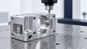
Every RFQ response says the same thing: “We do high-precision CNC machining.” Every supplier deck has a photo of a five-axis machine and a CMM. None of that tells you whether the parts you need — at your tolerance, in your material, at your volume — will actually come off the line consistent and correct.
“High-precision” is not a certificate you can check. It’s a claim you have to test, feature by feature, against real production data. Below are five places where buyers routinely get burned by taking the claim at face value, what the underlying engineering actually says, and what to put in your RFQ or quality agreement instead.
1. The “We Can Do ±0.005mm” Promise Rarely Survives Production Volume
A tolerance claim refers to a supplier’s statement that a given process can hold a specified dimensional range — but the claim only means something when it’s tied to a specific feature, material, batch size, and measurement method; stated in isolation, it’s marketing, not a spec.
±0.005mm sounds impressive until you do the math. That’s a total tolerance band of only 0.010mm — 10 microns. Using a standard process-capability target of Cp = 1.33, the process standard deviation needed to hold that band reliably works out to:
σ ≤ 0.010 / (6 × 1.33) ≈ 0.00125mm, or about 1.25 microns [NIST Process Capability Handbook]
That’s before you subtract measurement uncertainty, tool wear, thermal drift, or fixture repeatability. And thermal drift alone can eat a meaningful chunk of that margin: aluminum has a linear expansion coefficient of roughly 23 µm/m·°C, so a 100mm feature moves about 2.3 microns for every 1°C swing in shop temperature [NIST, Improving CNC Machining Accuracy Through Thermal Model-Based Control]. On a ±5-micron single-sided tolerance, that’s nearly half your entire allowance, gone to a door being left open near the machine.
None of this means ±0.005mm is impossible. It means “we can do it” usually describes one of several very different realities: a single hand-tuned sample, a batch kept in spec only through 100% sorting, or a capability that holds on a simple OD but collapses on a deep bore or thin wall. The dangerous version isn’t the supplier who says no — it’s the one who says yes at a low price, ships a beautiful first article, and then manages the gap through rework and quiet late deliveries.
Maßnahme: For any feature at ±0.010mm or tighter, don’t ask “can you hold this?” Ask for Cpk/Ppk data from a production-representative run — same machine, fixture, tooling, and material lot you’ll actually use — plus the stated measurement uncertainty of the gauge that generated the numbers.
2. Tighter Tolerance Is Not the Same Thing as Better Quality
Tolerance refers to the allowable variation in a dimension before it stops performing its function — which means a tolerance only has value if it’s tied to an actual failure mode, not to how the part “should” look on a drawing.
Collapsing a tolerance from ±0.10mm to ±0.01mm on a dimension that doesn’t affect fit, sealing, load path, or interchangeability adds cost, cycle time, and scrap risk without improving the finished product at all. The right engineering question isn’t “how tight can this shop go” — it’s “how much variation does this feature actually tolerate in assembly and in service” [ASME Y14.5, GD&T Fundamentals].
There’s a second trap here: dimensional tolerance and geometric tolerance solve different problems. A hole can be perfectly on-size and still be badly positioned relative to the mounting pattern. A shaft can be within diameter tolerance and still have runout that destroys a bearing fit. Tight ± numbers on a print don’t substitute for GD&T when the function actually depends on flatness, perpendicularity, position, or profile [ASME Y14.5]. For everything that isn’t functionally critical, general tolerancing standards like ISO 2768 do the job — for example, ISO 2768-f (fine class) allows ±0.10mm for a 6–30mm nominal, versus ±0.50mm under the coarse class [ISO 2768 application guidance, Xometry / Werk24].
Over-tightening tends to show up as a cost increase the supplier can’t clearly explain — is it grinding, honing, a dedicated fixture, or just 100% inspection — while the dimension that actually matters for assembly, a datum relationship or a sealing face, never got called out with GD&T at all.
Maßnahme: Tolerance the drawing by function, not by habit. For every tight tolerance on the print, be able to answer two questions: what failure does it prevent, and how will it be measured reliably? If you can’t answer both, it’s a candidate for loosening.
3. A CMM Report Saying “Pass” Doesn’t Mean the Part Actually Conforms
A CMM report refers to a set of measured values against nominal and tolerance — it is not, by itself, a conformance decision; that decision depends on the measurement method, the measurement uncertainty, and an agreed decision rule, none of which show up if the report only prints PASS/FAIL.
This is where I ran my own small experiment while researching this piece. I pulled CMM reports from two suppliers quoting the same bore feature — nominally identical part, same drawing, same Ø10.000 ±0.005mm callout — and compared what each report actually contained. One report listed a single measured value, a pass stamp, and nothing else. The other listed the datum scheme, probe diameter, ambient temperature at time of measurement, CMM program version, and a stated expanded uncertainty of ±0.003mm. Both said “pass.” Only one of them gave me enough information to know what that pass actually meant. That gap — not the machine, not the operator — was the real quality risk in the transaction.
The standard governing this is ISO 14253-1, which requires that conformity and non-conformity decisions account for measurement uncertainty, particularly when a result sits near a specification limit [ISO 14253-1]. Consider a bore spec of Ø10.000 ±0.005mm (limits: 9.995–10.005mm). A supplier’s CMM reads 10.004mm — technically inside the upper limit. But if the measurement system’s expanded uncertainty is ±0.003mm, the true value could plausibly sit above 10.005mm. A bare “in tolerance, therefore pass” rule can quietly accept a bad part.
A long-standing rule of thumb is the 4:1 Test Uncertainty Ratio — measurement uncertainty should be at least four times smaller than the tolerance band [NIST, Guidelines for Expressing Measurement Uncertainties and the 4:1 TUR]. It’s a useful floor, but it doesn’t eliminate risk on its own; results near the limit, the decision rule applied, and the consequence of a wrong call all still matter.
Maßnahme: Stop asking for “a CMM report.” Ask for the datum scheme, program version, instrument calibration traceability, stated measurement uncertainty, and the conformity decision rule (ISO 14253-1 or an equivalent written agreement) — especially for any result close to a limit.
4. ISO 9001 Certifies a Management System, Not a Micron-Level Machining Capability
ISO 9001 certification refers to independent confirmation that a supplier’s quality management system meets a documented standard — document control, corrective action, internal audits, calibration records — not confirmation that the shop can hold your specific tolerance on your specific geometry [ISO 9001:2015].
ISO’s own explanatory material is explicit that the standard defines requirements for a quality management system, not operational specifications for a given factory [ISO, ISO 9001 Explained]. It says nothing about five-axis capability, grinding or honing equipment, temperature-controlled inspection rooms, or whether a shop can repeatably hit Ra 0.2 µm or a 0.01mm position tolerance. A certificate confirms the paperwork is disciplined. It does not confirm the machine shop floor can do what your drawing needs.
This distinction matters in practice: a supplier can have excellent document control and a strong internal-audit trail and still have zero experience with thin-wall aluminum housings, deep small-diameter bores, or post-anodize dimensional control. ISO 9001 tells you the shop is good at managing problems once they’re found — not that it’s capable of preventing a micron-level drift in the first place [NIST Process Capability Handbook].
Maßnahme: Treat ISO 9001 as a floor for supplier qualification, not a ceiling. For precision work, separately request evidence in five areas: comparable-part history, process capability data (Cpk/Ppk), measurement equipment and uncertainty documentation, in-process controls (first-article checks, tool-life management, reaction plans), and demonstrated production capacity at your volume.
5. Anodizing Changes Dimensions — Most Purchase Orders Never Account for It
Anodizing refers to an electrochemical process that grows an oxide layer on aluminum, part of which forms inward into the base metal and part of which builds outward — meaning it is a dimensional operation, not just a color or corrosion-resistance finish, and it will move every bore, OD, thread, and mating surface it touches.
Under MIL-PRF-8625, the U.S. military-industry reference spec for aluminum anodizing, Type III hardcoat film thickness typically runs about 0.0005–0.0045 inches, roughly 12.7–114.3 microns [MIL-PRF-8625F, Anoplex reference]. Engineering practice commonly estimates that roughly half of that thickness grows outward, though the true split depends on alloy, process parameters, masking, and the specific anodizing line — so it has to be confirmed with the actual finisher, not assumed [Chem Processing, Planning for Anodize Buildup].
Run the numbers on a real bore. Say a hardcoat film is 50 microns thick and roughly half of it grows outward — that’s about 25 microns building inward on each wall of the hole, for a total bore reduction of:
25 µm + 25 µm = 50 µm = 0.050mm
A bore machined to Ø10.000mm before anodizing could land near Ø9.950mm afterward. Against a finished-part tolerance of Ø10.000 ±0.010mm — a 0.020mm total band — that shift is 2.5 times the entire tolerance. This isn’t an edge case; it’s the default behavior of hardcoat anodizing on any dimension in the same order of magnitude as the film [Chem Processing; MIL-PRF-8625F].
The failure mode this produces in the field is predictable: bearing bores come back too tight to press-fit, slide fits seize, threads won’t accept a fastener at spec torque, and a supplier’s pre-anodize inspection sign-off has nothing to do with the part that actually shows up in your warehouse.
Maßnahme: Specify, in writing, whether every critical dimension applies before or after anodizing, the anodize type and film-thickness range, which surfaces must be masked, and require the final dimensional report to be taken post-finish — not pre-finish.
Across all five of these, the pattern is the same: a supplier’s confident answer is not evidence. Evidence is a number, tied to a method, tied to a measurement uncertainty, generated under conditions that match how the part will actually be produced. That’s a higher bar than most RFQs ask for — but it’s the only bar that actually protects a purchase order.
Häufig gestellte Fragen
A: Not usually. A nominal CAD model typically defines ideal geometry, not the allowed deviation, datum structure, surface finish, material condition, or post-processing state. Different suppliers will fill those gaps differently — one may default to ISO 2768-m, another to their own “standard shop tolerance.” Provide a controlled drawing or model-based definition (MBD) with GD&T, general tolerances, material and finish callouts, and a stated priority between drawing, model, and PO.
A: No. A single approved sample proves a part was made correctly once, under one specific set of conditions. It doesn’t prove statistical process control, a centered process average, or stability across tool changes, shift changes, or material lots. This is exactly the gap PPAP-style production-part-approval processes exist to close — requiring production-representative runs and consecutive-sample capability data instead of a single hand-built piece.
A: A common starting rule of thumb is a 4:1 Test Uncertainty Ratio — the measurement system’s uncertainty should be roughly four times smaller than the tolerance band. It’s a useful screening threshold, not a guarantee; results close to the specification limit still need an explicit decision rule
A: Dimensional tolerance (a ± number) controls how big or small a single measurement can be. GD&T controls geometric relationships — flatness, position, perpendicularity, runout — relative to a defined datum structure. A part can pass every dimensional check and still fail to assemble if the geometric relationships between features aren’t controlled.
A: At minimum: the applicable standard (e.g., ASME Y14.5), datum scheme, the measurement method and equipment for each critical feature, whether tolerances apply before or after heat treat/coating, required capability data (Cpk/Ppk) from production-representative conditions, and the conformity decision rule to be used when a result lands near a limit.
A: Yes, as a baseline filter — it’s a reasonable signal of document control, corrective-action discipline, and traceability. It just shouldn’t be treated as proof of precision machining capability. Use it to qualify a shop, then separately verify comparable-part experience, measurement capability, and process data for the specific feature you need.