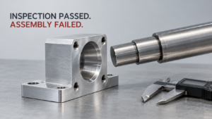
If you buy CNC machined hardware for a living, you’ve seen this scenario: the supplier sends back an inspection report with a beautiful Ra 0.4 µm reading, and the part still doesn’t fit, doesn’t seal, or doesn’t pass your incoming QC. This isn’t a fluke or a bad supplier. It’s a structural misunderstanding baked into how roughness callouts get written on drawings — and it costs buyers real money on both ends: rejected parts on one side, over-specified drawings that inflate quotes on the other. Let’s break down what Ra actually controls, where it stops controlling anything, and how to write callouts that protect you without turning every RFQ into a grinding job.
Surface Roughness vs. Dimensional Tolerance: The Core Confusion
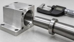
Surface roughness refers to the microscopic peak-and-valley texture left on a surface by a cutting tool, abrasive, or forming process, measured after filtering out longer-wavelength deviations — it is not a measurement of size, shape, or position. Dimensional tolerance controls actual size (diameter, length, thickness), while form and positional accuracy — flatness, roundness, cylindricity, profile, position, runout — are governed separately under GD&T or ISO GPS [ASME B46.1]. ASME’s own standard defines surface texture as roughness, waviness, and lay only, explicitly excluding dimensional error, hole position error, flatness, and cylindricity from what a roughness number represents [ASME B46.1]. That means a supplier can hand you a spotless Ra 0.4 µm report on a shaft that’s still 0.018 mm oversize against a Ø20.000–20.010 mm callout, and the report isn’t wrong — it’s just answering a question you didn’t ask.
The problem side of this is obvious: buyers who write “Ra 0.8” as their only quality gate on a drawing are leaving size, roundness, and position completely uncontrolled. The opportunity side is less obvious but just as real — once you understand that Ra and dimensional control are independent, you can stop over-specifying roughness on non-critical faces (which inflates machining time and quote price for zero functional benefit) and instead spend that tolerance budget where it actually matters: sealing faces, bearing journals, mating bores.
Action: Audit your last five drawings — if any surface has only a roughness callout and no explicit dimensional or geometric tolerance tied to it, fix that before your next RFQ goes out.
Ra, Rz, and Waviness — Three Numbers That Tell Completely Different Stories
Ra (Arithmetic Mean Roughness) refers to the average absolute deviation of the roughness profile from the centerline, which by definition smooths out the effect of isolated deep scratches, peaks, or pits — it’s an average, not a worst-case number [Hubs Knowledge Base]. Rz, by contrast, tracks peak-to-valley height and is far more sensitive to localized gouges, tool marks, and sealing-relevant defects [Hubs Knowledge Base; Astropak]. There is no fixed conversion formula between the two — the commonly cited rule of thumb that Rz ≈ 4–8× Ra is only useful for early process conversations, never for acceptance criteria [Hubs Knowledge Base; ISO 4287]. Waviness sits on top of both: it’s a longer-wavelength surface undulation caused by tool runout, spindle behavior, clamping distortion, thermal drift, or cutting force variation, and a part can measure Ra 0.4 µm locally while still carrying visible taper or bow along its length, because short-sampling-length roughness gauges may not capture that longer-wavelength error at all [ASME B46.1 poster; ANSI Blog on B46.1].
Here’s where the dialectic actually matters for sourcing: demanding a tighter Ra number as a proxy for “better quality” is a common but flawed shortcut — you might get a beautifully smooth surface that’s still tapered, barrel-shaped, or out of round. But there’s a genuine opportunity here too: if you specify Rz alongside Ra on sealing or fatigue-critical surfaces, you catch the localized defects that Ra averages away, often without raising the target Ra at all — meaning better functional protection at the same machining cost.
I ran this comparison myself while reviewing incoming inspection reports from three different suppliers on the same batch of hydraulic fittings. All three reports showed Ra values within 0.1 µm of each other and all “passed.” When I asked for Rz data on the same surfaces — which none of the suppliers had originally measured because the drawing didn’t call it out — the spread was much wider, and one supplier’s parts showed Rz values nearly double the others on the sealing face. Nothing in the original Ra-only spec would have flagged that difference, and it’s exactly the kind of gap that shows up later as field leaks, not incoming rejections.
Action: On any surface where sealing, fatigue, or coating adhesion matters, add an explicit Rz maximum next to your Ra maximum — don’t assume one implies the other.
What Ra Really Looks Like Across CNC Processes — and Why the Chart Is a Starting Point, Not a Guarantee
Typical process-based roughness ranges refer to the Ra bands that machine shops commonly cite in RFQ conversations and cost estimation, not a guaranteed capability for any specific material, geometry, or machine condition [Hubs Knowledge Base; Baetro Machining]. Conventional CNC milling typically lands at Ra 1.6–6.3 µm, fine milling/finish passes at Ra 0.4–1.6 µm, conventional turning at Ra 0.8–3.2 µm, and fine turning at Ra 0.2–0.8 µm [Hubs Knowledge Base; Inovatec Machinery]. Reaming generally produces Ra 0.8–3.2 µm, grinding 0.1–1.6 µm, honing 0.05–0.8 µm, and polishing/lapping/superfinishing 0.01–0.4 µm [Inovatec Machinery; 3Q Machining]. In commercial quoting, Ra 3.2 µm is frequently used as the default “as-machined” baseline, with Ra 1.6 or 0.8 µm achievable on stable machines with sharp tooling and added finishing passes, and Ra 0.4 µm reachable on simple, rigid features [Hubs Knowledge Base; Norck].
The risk in treating this chart as gospel is that actual Ra depends on a long list of variables — material grade, heat treatment state, tool wear, tool runout, clamping rigidity, wall thickness, toolpath, coolant, cutting speed, feed, nose radius, stepover, machine dynamics, and inspection method [Hubs Knowledge Base; Baetro Machining]. Two suppliers running the “same” process on the “same” nominal part can land in different bands. The opportunity is that this variability cuts both ways in negotiation: if your functional requirement genuinely only needs Ra 1.6 µm, you don’t need to pay for a grinding or honing operation just because a template spec sheet says “smooth finish” — conventional milling or turning with a finishing pass gets you there at a fraction of the cost.
Action: Before specifying a finishing process (grinding, honing, polishing) by name, confirm the actual Ra/Rz your function needs — you may be able to hit it with a finishing pass on the primary CNC process and skip a secondary operation entirely.
Material Choice Changes the Real Numbers More Than Most RFQs Admit
Material-driven roughness variation refers to the fact that achievable Ra at a given process step shifts significantly by material family, grade, and condition — which is why “aluminum” or “stainless steel” alone is not a specific enough callout to support a stable quote [Worthy Hardware; Baetro Machining]. Aluminum alloys with good machinability, sharp/polished tooling, and controlled built-up-edge typically hit Ra 1.6–3.2 µm in conventional milling/turning and Ra 0.4–0.8 µm with finishing passes, but 6061-T6, 7075-T6, and cast aluminum behave differently enough that grade and condition need to be on the drawing [Worthy Hardware; Baetro Machining]. Stainless steel commonly reaches Ra 1.6–3.2 µm conventionally and Ra 0.4–0.8 µm with stable fine turning, milling, or grinding, but work hardening, cutting temperature, chatter, and built-up edge make consistent low-Ra results harder — and 304, 316, 17-4PH, 420, 430, and duplex grades are not interchangeable in this regard [FS Fab; Baetro Machining]. Carbon and alloy steels in annealed or tempered condition typically achieve Ra 1.6–3.2 µm conventionally and 0.4–0.8 µm finished, but hardened, carburized, or nitrided parts usually need grinding, honing, or superfinishing to hit final dimensional and surface targets, with added attention to grinding burn and residual stress [Inovatec Machinery; Baetro Machining].
Titanium’s low thermal conductivity concentrates cutting heat at the tool and makes it prone to chatter and tearing, so Ra 1.6–3.2 µm is a realistic common target, with Ra 0.8–1.6 µm achievable only under tighter tooling, toolpath, and cooling control — and thin-wall or five-axis titanium geometries can see machining time, scrap risk, and inspection cost rise sharply when low Ra is demanded [Baetro Machining; Worthy Hardware]. Free-machining brass, by contrast, often turns easily to Ra 0.8–1.6 µm conventionally and 0.2–0.8 µm finished, though lead-free brass and thin-wall or cosmetic parts can behave differently [FS Fab; Worthy Hardware]. Engineering plastics complicate things further: POM, nylon, PEEK, PTFE, PC, ABS, and their reinforced variants cut, absorb moisture, and release residual stress differently, so a plastic part can measure Ra 0.8–1.6 µm and pass dimensional inspection on the bench, then shift out of tolerance after unclamping or after moisture equilibration [Baetro Machining; Hubs Knowledge Base].
The problem here is that generic material callouts (“aluminum,” “stainless steel,” “nylon”) leave suppliers guessing about achievable roughness, which shows up later as quote disputes or rejected first articles. The opportunity is that specifying grade and condition precisely often lets a supplier propose a cheaper process path — because they know exactly what the material will actually do instead of quoting conservatively for the worst case.
Action: Never write a bare material name on a drawing that also carries a roughness callout — always pair it with grade, temper/condition, and for plastics, moisture/conditioning state at inspection.
Six Real Failure Patterns Where Low Ra Passed Inspection but the Part Still Failed — and the Drawing Fix for Each
A “Ra-passes-but-part-fails” pattern refers to any case where a surface meets its roughness callout on paper while a different, uncontrolled characteristic causes functional failure — and these patterns recur often enough in incoming inspection that they’re worth naming individually [ISO 4287; ASME B46.1]. First, a precision-turned shaft can measure Ra 0.4 µm while its actual diameter sits outside a Ø20.000–20.010 mm tolerance band, because Ra reflects local texture, not average size [ISO 4287]. Second, a ground shaft can hit Ra 0.2 µm while carrying taper, barrel, or hourglass shape from wheel wear, thermal expansion, or center clamping — short-sampling-length Ra readings don’t capture full-length cylindricity error [ASME B46.1 poster]. Third, a reamed or honed bore can be smooth and within diameter tolerance while being triangular, multi-lobed, off-axis, or non-perpendicular to a datum face — pin holes, bearing bores, and hydraulic bores need roundness/cylindricity and position controlled independently of roughness [ISO 4287; ASME B46.1].
Fourth, because Ra is an average, an isolated deep scratch or pit may not raise the Ra number significantly, yet it can trigger seal leakage, corrosion initiation, fatigue cracking, or coating defects — Rz is more sensitive to these extremes, but explicit defect-prohibition language is still needed for scratches, burrs, or drag marks [Hubs Knowledge Base; ISO 4287]. Fifth, a milled or ground sealing face can measure Ra 0.8 µm while failing flatness due to clamping distortion, residual stress release, heat input, or insufficient part rigidity — sealing performance typically depends on the combined control of flatness, waviness, roughness, Rz, and lay direction, not one Ra value [ASME B46.1; ANSI Blog]. Sixth, polishing or vibratory finishing lowers Ra but can round sharp edges, enlarge bores, locally sink flat surfaces, or alter precision fillets and transitions — for bearing seats, sealing faces, mating bores, and functional edges, final dimensions and GD&T should be verified after the finishing operation, and in some cases the drawing should explicitly restrict method, e.g. “no hand polishing” or “grinding only to final roughness” [Hubs Knowledge Base; ISO 1302].
The takeaway across all six is dialectical in a very practical way: the problem is that a single roughness number creates a false sense of completeness on a drawing, but the opportunity is that each failure pattern maps to a specific, cheap fix — one added callout line, not a redesign. Buyers who add these lines up front spend a little more time on drawing review and save significantly more on rejected first articles and field failures later.
Action: For any functional surface — sealing face, bearing journal, precision bore — write dimension, form/position tolerance, Ra, Rz, and lay direction as five separate lines, not one roughness number standing in for all of them. A workable template looks like:
Ø30 g6
Cylindricity 0.008 mm
Ra 0.4 µm MAX
Rz 3.2 µm MAX
Lay: circumferential
No tears, burrs, scratches, or chatter marks
Note also that ISO 1302:2002, ISO 4287:1997, and ISO 4288:1996 — the standards governing surface texture symbols, terminology, and evaluation rules — are all listed as withdrawn on the ISO website, with ISO 21920 as the current successor series [ISO 21920 successor note]. If your contract or customer drawings specifically call out the older standards, keep using them as written; if you’re starting a new project and have the choice, referencing ISO 21920 alongside the legacy standards avoids ambiguity down the line.
FAQ
A: No. Ra and dimensional tolerance are independent characteristics — a smooth surface can still be oversize, undersize, or out of round. Always require dimensional and GD&T results alongside roughness data, especially on a first article.
A: Not for acceptance purposes. The commonly cited Rz ≈ 4–8× Ra range is only useful for rough process planning conversations, not for drawing callouts or quality gates.
A: Yes. Achievable Ra at any given process step varies significantly by material grade and condition — “aluminum” or “stainless steel” alone isn’t specific enough for a supplier to commit to a roughness target reliably.
A: Yes. Achievable Ra at any given process step varies significantly by material grade and condition — “aluminum” or “stainless steel” alone isn’t specific enough for a supplier to commit to a roughness target reliably.
A: You need to specify this explicitly. Anodizing and plating change the original machined surface, so an unqualified “Ra 0.8 µm” callout leaves the measurement condition ambiguous between supplier and inspector.
A: They’re listed as withdrawn by ISO, with ISO 21920 as the current successor series. If your customer contract or existing drawings specify the older standards, follow that specified version; for new projects where you have a choice, referencing the current ISO 21920 series alongside is the safer path.