If your RFQ says “Ø25 mm” and nothing else, you haven’t specified a part. You’ve specified a target that a machine shop will hit somewhere between 24.9 and 25.1 mm, and you won’t know which end you got until the parts show up and either don’t fit or fall out. For any feature that mates, rotates, locates, seals, or carries torque, the diameter is the least important number on the drawing. What actually determines whether the part works is the fit class, the datum structure, the geometric tolerances, the surface finish, the material condition, and whether the dimension applies before or after coating [ISO 286].
This guide breaks down the five things procurement teams get wrong most often when buying toleranced parts, and what to write instead.
1. A Nominal Diameter Alone Is Not a Purchasable Specification
A dimensional tolerance refers to the allowable range around a nominal size within which a part is still considered conforming — and without one, a supplier has no legal basis for rejecting an out-of-spec part, and you have no basis for rejecting theirs. ISO 286 is the standard most of the world uses to define this range for cylindrical holes and shafts, using a letter-plus-number code such as H7 or g6: the letter sets where the tolerance band sits relative to the nominal size (basic deviation), and the number sets how wide the band is (IT grade) — the lower the number, the tighter the tolerance [ISO 286]. In an H7/g6 fit, for example, the hole’s minimum size equals the nominal size, and the shaft always sits below nominal, so the two parts are guaranteed to have clearance [Machining Doctor].
The practical risk of skipping this is that “the same” nominal size can be produced correctly by three different suppliers and still not be interchangeable, because each one picked its own tolerance band by default machine capability rather than by function. The opportunity side is that once a tolerance band is written down, it becomes a contract term — it’s the difference between “close enough” and “out of spec, rework at supplier’s cost.” Standardizing on ISO 286 (or ASME B4.1 for inch-based US supply chains) also lets you use catalog tooling, gauges, and reamers instead of custom ones, which is usually the cheaper route for mid-volume production [Engineers Edge].
Action tip: Never release a drawing with a bare nominal diameter on a mating feature. At minimum, add the ISO fit code (e.g., Ø25 H7); for anything going into PPAP, FAI, or a regulated program, spell out the actual limit dimensions in millimeters so there’s no ambiguity across tools or standard revisions.
2. ISO Fits Only Work When You Pick Them by Function, Not by Habit
A fit class refers to the combination of a hole tolerance and a shaft tolerance that predicts — before a single part is machined — whether the assembled result will have clearance, interference, or something in between. Take Ø25 mm as a working example: an H7 hole on that diameter runs 25.000–25.021 mm, and pairing it with a g6 shaft (roughly 24.984–24.993 mm) produces a clearance of about 0.007–0.037 mm, which is the textbook “precise sliding” fit used for guide pins and lightly loaded rotating shafts [Machining Doctor]. Swap the same H7 hole to an h6 shaft (24.987–25.000 mm) and the clearance drops to 0–0.034 mm — good for locating parts that still need to come apart by hand, but not safe for anything that has to spin freely under heat or contamination [Engineers Edge]. Go the other direction to H7/p6 and you’re no longer talking about clearance at all — the shaft’s tolerance band sits entirely above nominal, which is what creates the interference used for press-fitting gears, hubs, and bushings [Jiga].
The dialectical part here is that “tighter” isn’t automatically “better.” Over-specifying H7/g6 everywhere makes machining more expensive and doesn’t buy you anything if the part is a bolted bracket that just needs to line up with a hand-turned fastener. Under-specifying it on a bearing shaft creates creep, fretting, or a part that loosens itself over thousands of load cycles. The real opportunity is that once you match the fit to the actual function — free assembly, guided sliding, accurate locating, transition, or interference — you can relax tolerances everywhere they aren’t load-bearing and tighten them only where they matter, which is usually a net cost reduction across a multi-feature part [ISO 286].
One more wrinkle worth budgeting time for: ISO 286 and the US ANSI/ASME B4.1 system are not directly interchangeable. ASME B4.1 uses its own classes (RC, LC, LT, FN) built around inch limit dimensions, and even where an ISO fit and an ANSI class describe a similar function, the resulting min/max clearance numbers won’t match exactly because the underlying tables and preferred series differ [ASME B4.1]. If you’re running a mixed US/ISO supply base, don’t translate fit codes by name — recalculate the actual limit dimensions for both systems and put both on the drawing or inspection spec [Ames Web].
Action tip: Before writing a fit code, answer one question first — “what does this feature actually do: slide, locate, rotate, or hold by friction?” — then select from H7/g6 (sliding), H7/h6 (locating), H7/k6–n6 (transition), or H7/p6–s6 (interference) based on that answer, not on whichever code appeared on the last drawing.
3. Bearing Seats, Threads, and Press Fits Each Need Their Own Spec Language — Not a Borrowed H7
A bearing seat tolerance refers to the shaft and housing fit selected specifically for a rolling-element bearing’s load direction, speed, and precision class — and it cannot be approximated by copying the H7 used elsewhere on the same drawing. SKF’s own guidance is explicit that its published seat tolerances are for standard operating conditions only and have to be re-evaluated against actual load, speed, housing material, and temperature for anything outside that envelope [SKF]. The general rule is that whichever bearing ring rotates relative to the load needs the tighter fit, because a loose ring under rotating load will creep around its seat — so a rotating inner ring typically drives a tighter shaft fit (h6 up to m6 or n6), while a rotating outer ring drives a tighter housing bore fit [SKF]. Specifying only “H7 bore, bearing per catalog number” and leaving the rest to the supplier is one of the more common ways bearing seats fail early.
Threads are a separate problem entirely — and this is where I’ve personally seen the most avoidable failures. On a supplier audit I ran for a batch of M10 fastener bosses, the drawing had listed the thread as “M10 H7,” borrowing the hole-and-shaft fit code because that’s what the rest of the drawing used. The tapped holes measured within that generic tolerance band on a bore gauge and were signed off — but the go/no-go thread gauge failed on roughly a third of the lot, because H7 describes a cylindrical hole’s diameter, not a thread’s pitch diameter, flank angle, or lead error, none of which ISO 286 covers [ISO 965]. The fix cost us a re-tap pass and a week of schedule; writing “M10 × 1.5 – 6H” on the drawing in the first place would have cost nothing. For inch threads, the equivalent standard is ASME B1.1, with 2A/2B as the common commercial-grade external/internal fit and 3A/3B for tighter, lower-play applications [ASME B1.1].
Press fits carry the same trap in the other direction — “Press Fit” or “Light Press Fit” on a drawing defines nothing measurable. The interference has to be stated as a min/max range, because the axial holding force it produces follows roughly F = μ·p·π·D·L (friction coefficient × contact pressure × contact area), and contact pressure itself depends on material stiffness, wall thickness, and whether the hub is solid or hollow — not just on the nominal interference number [Jiga]. A steel shaft into a thick steel hub tolerates far more interference than the same nominal fit pressed into a thin aluminum housing, which is prone to local yielding or cracking under the same numbers [Wevolver].
Action tip: Treat bearing seats, threads, and press fits as three separate specification problems, not variations on ISO 286. Pull the bearing manufacturer’s seat table for the specific bearing and load direction, use ISO 965 or ASME B1.1 thread callouts exactly as written (e.g., M10×1.5-6H, 1/4-20 UNC-2B), and require a stated min/max interference range — never just the word “press” — on any friction-fit feature.
4. Coatings, Temperature, and Surface Finish Quietly Rewrite the Tolerance You Thought You Bought
A post-process dimension refers to the final size of a feature after plating, anodizing, or heat treatment has been applied — and if your drawing doesn’t say whether the toleranced dimension applies before or after that process, the supplier will assume whichever is more convenient for them, not for your assembly. Coating adds material to external diameters and removes clearance from internal ones; as a rough rule, a uniform coating thickness t adds about +2t to a shaft’s diameter and subtracts about −2t from a bore’s diameter, though hard anodizing in particular doesn’t behave this way cleanly, since the oxide layer both consumes base metal and grows outward at the same time [Rapid Efficient]. Temperature does something similar through thermal expansion: for a Ø50 mm steel hub heated 80°C to enable a hot-press assembly, using a typical steel expansion coefficient of about 12×10⁻⁶/°C, the bore grows by roughly ΔD = 12×10⁻⁶ × 50 × 80 = 0.048 mm — small on paper, but often the entire difference between a fit that goes together by hand and one that requires a press [Jiga].
I ran into the coating version of this problem directly while reviewing an incoming inspection report for a batch of hard-anodized aluminum housings with a bearing bore spec’d at Ø25 H7. Every piece had measured in-tolerance before anodizing and passed first-article. After a 20–25 µm anodize layer was applied, the bores came back roughly 0.02–0.03 mm undersized for the bearing outer race, and a portion of the lot needed a final honing pass just to get the bearings seated. Nothing on the drawing had said “H7 applies before anodizing” or “final-hone after anodize” — it just said H7, and the shop reasonably machined to that number pre-coating. The fix was two lines of text on the drawing (“DIMENSION APPLIES AFTER ANODIZE, COATING THICKNESS 20–25 µm, FINAL-HONE BEARING SEAT AFTER COATING”), and it never recurred on later revisions.
Surface finish plays a similar quiet role, especially on sealing and press-fit surfaces. Parker’s O-Ring Handbook recommends static sealing surfaces stay below 32 µin RMS in general, tightening to 16 µin RMS max for static gas seals on end faces — and it notes that the average roughness number isn’t the whole story, since directional tool marks, cross-hatching, or a single scratch can create a leak path that a good Ra number wouldn’t catch [Parker O-Ring Handbook]. On press fits, rougher surfaces get partially flattened during assembly, so the geometric interference measured before assembly typically overstates the effective interference after — but too rough a surface also increases press-in force variability and the risk of galling [Jiga].
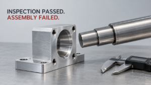
Action tip: For every coated, plated, or heat-treated dimension, write explicitly whether it applies before or after that process, state the coating thickness range, and specify which surfaces need masking or final machining afterward — this single line item prevents most of the “parts passed inspection but don’t fit” complaints that show up after coating.
5. The Eight Tolerance Mistakes That Show Up Most on Procurement Drawings
A specification gap, in this context, refers to any place where a drawing states a number but leaves the functional intent — how tight, how measured, in what condition — up to interpretation, and interpretation is where cost and rework hide. Across the patterns above, eight repeat constantly: bare nominal diameters with no fit code; “press fit” with no stated interference range; H7 applied to every hole regardless of function; ISO fit codes mistakenly used on threads; missing datum structure and GD&T; ignoring roundness, cylindricity, and runout even when two-point diameter checks pass; ignoring pre/post-coating dimensional state; and leaving assembly method and inspection conditions undefined [ASME Y14.5]. None of these require exotic engineering knowledge to fix — they require a checklist applied consistently before a drawing goes out for quote.
The data-driven argument for doing this work upfront rather than catching it at incoming inspection is straightforward: the cost of adding a line of text to a drawing is close to zero, while the cost of a failed press-fit assembly, a stripped thread gauge, or a bearing seat that creeps in service is measured in scrapped parts, missed ship dates, and — for anything under PPAP or FAI — a formal deviation process [Jiga] [ASME Y14.5]. The opportunity is that a tighter RFQ spec sheet actually speeds up quoting, because suppliers stop guessing at your intent and stop padding their quotes for the risk of an ambiguous call-out.
Action tip: Build a standard RFQ tolerance checklist — basic size, ISO fit code, final limit dimensions on critical features, functional datum structure, roundness/cylindricity/runout requirements where relevant, material and heat-treat state, surface finish, coating type and thickness with pre/post-coating dimensional state, bearing model and load direction where applicable, thread standard and class, assembly method, and inspection method with sample plan — and require every supplier to quote against the same fields, every time.
FAQ
A: H7/g6 always produces a small positive clearance (roughly 0.007–0.037 mm on a Ø25 mm feature), which makes it suitable for parts that need to slide or rotate lightly. H7/h6 has a theoretical minimum clearance of zero, so it’s meant for accurate locating features you still want to disassemble by hand, not for anything that needs guaranteed running clearance under heat, dirt, or load — using it on a rotating shaft can cause binding once real-world tolerances stack up.
A: No — “press fit” alone doesn’t specify the minimum or maximum interference, the allowed press-in force, the assembly method (cold press, hot press, hydraulic), or whether lubrication is permitted, so two suppliers can both deliver “press fit” parts with very different holding force and failure risk. Always state a min/max interference range and the intended assembly method on the drawing.
A: They’re not directly interchangeable. ISO 286 and ASME B4.1 use different tables, different preferred series, and different units (metric vs. inch), so even fits that describe a similar function — like a running clearance fit — won’t produce identical minimum and maximum clearance numbers. For mixed US/ISO supply chains, list the actual limit dimensions rather than relying on the fit codes to translate.
A: ISO 286 governs cylindrical (non-threaded) hole and shaft diameters. Thread function depends on pitch diameter, flank angle, pitch, and lead error, none of which a diameter-based fit code captures — which is why threads use ISO 965 (metric, e.g., 6H/6g) or ASME B1.1 (inch, e.g., 2A/2B) instead.
A: As a rough approximation, coating adds about twice the coating thickness to an external diameter and removes about twice the coating thickness from an internal bore, though hard anodizing behaves less predictably because it both consumes and grows the base material. A drawing should always state whether a toleranced dimension applies before or after coating, and give a coating thickness range.
A: At minimum: the full bearing model and precision class, which ring (inner or outer) carries the rotating load, radial/axial load and speed, housing and shaft material, roundness/cylindricity/runout of the seat, surface finish, and the intended mounting method (cold press, hot mount, hydraulic). published seat tolerances are for standard conditions only and need re-verification against your actual application.